System and method for measuring and correcting astigmatism using laser generated corneal incisions

a laser generated cornea and astigmatism technology, applied in laser surgery, medical science, diagnostics, etc., can solve the problems of limited accuracy, inability to eliminate bias, and inability to use ink marks to reduce the effect of cyclotorsion, so as to reduce or eliminate systematic errors during measurement

Pending Publication Date: 2022-06-09
LENSAR LLC
View PDF0 Cites 0 Cited by
  • Summary
  • Abstract
  • Description
  • Claims
  • Application Information

AI Technical Summary

Benefits of technology

[0018]One or more aspects of the present invention allow for reducing or eliminating systematic errors during measurement of the properties of an astigmatism axis of an eye.

Problems solved by technology

The use of ink marks reduces the effect of cyclotorsion on the astigmatism treatment; however, it is inconvenient—for best results, it requires a separate seating of the patient at a slit lamp—but still has limited accuracy because of the inevitable errors in manually placing the initial marks, and the “bleeding” of the marks as the tear film reacts with the marking ink.
Systematic error between instruments is due to fundamental differences in measurement technique, calibration, etc. and represents an irreducible bias between the two instruments.
No amount of averaging of repeated measurements can eliminate the bias.
However, this latter condition is not always met.

Method used


Image

  • System and method for measuring and correcting astigmatism using laser generated corneal incisions
  • System and method for measuring and correcting astigmatism using laser generated corneal incisions
  • System and method for measuring and correcting astigmatism using laser generated corneal incisions

Examples


Embodiment Construction

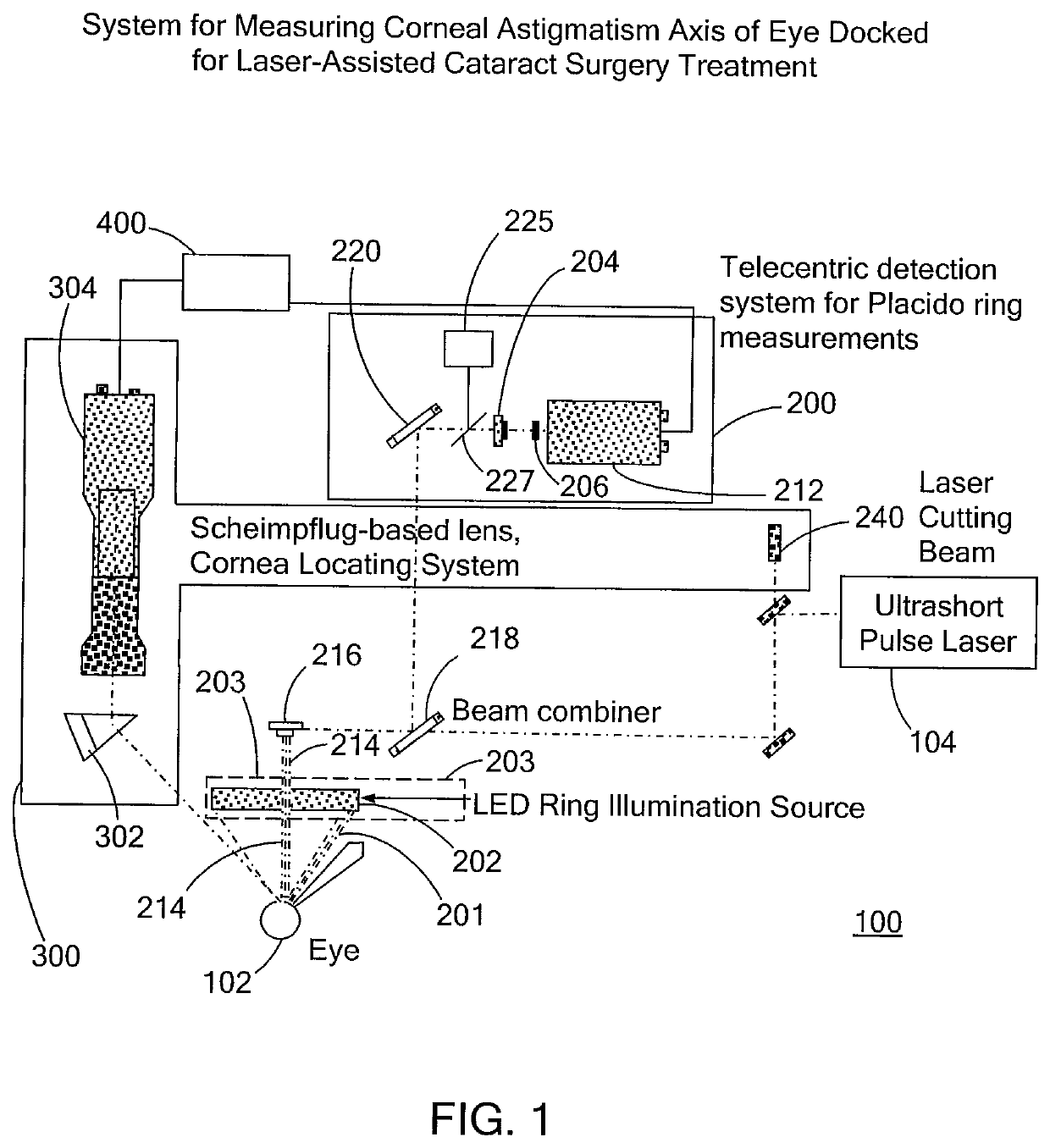
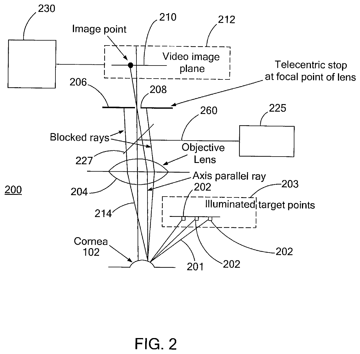
[0025]FIG. 1 schematically shows a measuring and treatment system 100 for measuring the corneal astigmatism axis and for performing an ophthalmological procedure on the eye 102 of a patient. The system 100 includes a keratometer 250 which includes a light generator 203 (dashed lines) and a telecentric detection system 200. The light generator 203 includes two light sources, each comprising a ring of 10-20 discrete LEDs 202. The telecentric detection system 200 is used for measuring concentric rings of the LEDs 202 and for alignment of the patient's eye with the keratometer. The system 100 also includes a Scheimpflug-based lens and cornea locating system 300, and a treatment laser system that includes a treatment laser 104.

[0026]In use, the patient typically lies on a gurney or a reclining surgical chair which is rolled into position under the optical head of the treatment laser 104. The keratometer 250 and the Scheimpflug-based lens and cornea locating system 300 may be designed to ...


PUM


Abstract

A laser system that includes a laser source emitting a laser beam along an axis and a keratometer. The keratometer includes a first set of individual light sources that are equally spaced from one another along a first ring and that direct a first light toward an eye and a second set of individual light sources that are equally spaced from another along a second ring and direct a second light toward the eye, wherein the first ring and said second ring are co-planar and concentric with one another about the axis. The laser system includes a telecentric lens that receives the first light and second light reflected off of the eye and a detector that receives light from the telecentric lens and forms an image. The laser system also includes a processor that receives signals from said detector representative of the image and determines an astigmatism axis of the eye based on the signals.

Description

[0001]This application claims the benefit of priority under 35 U.S.C. § 119(e)(1) of 1) U.S. Provisional Application Ser. No. 61 / 467,592, filed Mar. 25, 2011 and 2) U.S. Provisional Application Ser. No. 61 / 467,622, filed Mar. 25, 2011, and this application is a continuation-in-part application of U.S. patent application Ser. No. 13 / 017,499, filed Jan. 31, 2011 (now pending), which claims the benefit of priority under 35 U.S.C. § 119(e)(1) of U.S. Provisional Application Ser. No. 61 / 300,129, filed Feb. 1, 2010, the entire contents of each of the above mentioned patent applications and provisional applications is incorporated herein by reference.FIELD OF THE INVENTION[0002]The present invention relates to a system for performing an astigmatism measurement for the purpose of correcting astigmatism. The present invention also has to do with marking the measured axis of astigmatism with a laser-created mark.BACKGROUND[0003]In known procedures for correcting astigmatism, such as limbal re...

Claims


Application Information

Patent Timeline
Patent Type & Authority Applications(United States)
IPC IPC(8): A61B3/103A61B3/107A61F9/008
CPCA61B3/1035A61B3/107A61F9/00825A61F9/00827A61F2009/00887A61F2009/0087A61F2009/00872A61F2009/00889A61F2009/00853A61F9/00834A61F2009/00844
Inventor FREY, RUDOLPH W.
Owner LENSAR LLC
Why Eureka
Try Eureka