Conical rotation valve

Pending Publication Date: 2022-06-09
TI AUTOMOTIVE TECH CENT
View PDF16 Cites 0 Cited by
  • Summary
  • Abstract
  • Description
  • Claims
  • Application Information

AI Technical Summary

Benefits of technology

The objective of this patent is to create a rotary valve that is easy to adjust, has low leakage, and is durable.

Problems solved by technology

In addition, rotary valves require only little installation space.
However, the problem can arise that high frictional forces and thus increased wear occur in the case of a sealing contact between the valve core and the valve housing due to the required contact pressure.
If, on the other hand, the valve core is arranged in the valve housing with a clearance, the forces required for rotation and the wear are reduced, but undesirable leakage can occur via the gap between the valve housing and the valve core.

Method used


Image

  • Conical rotation valve
  • Conical rotation valve
  • Conical rotation valve

Examples


first embodiment

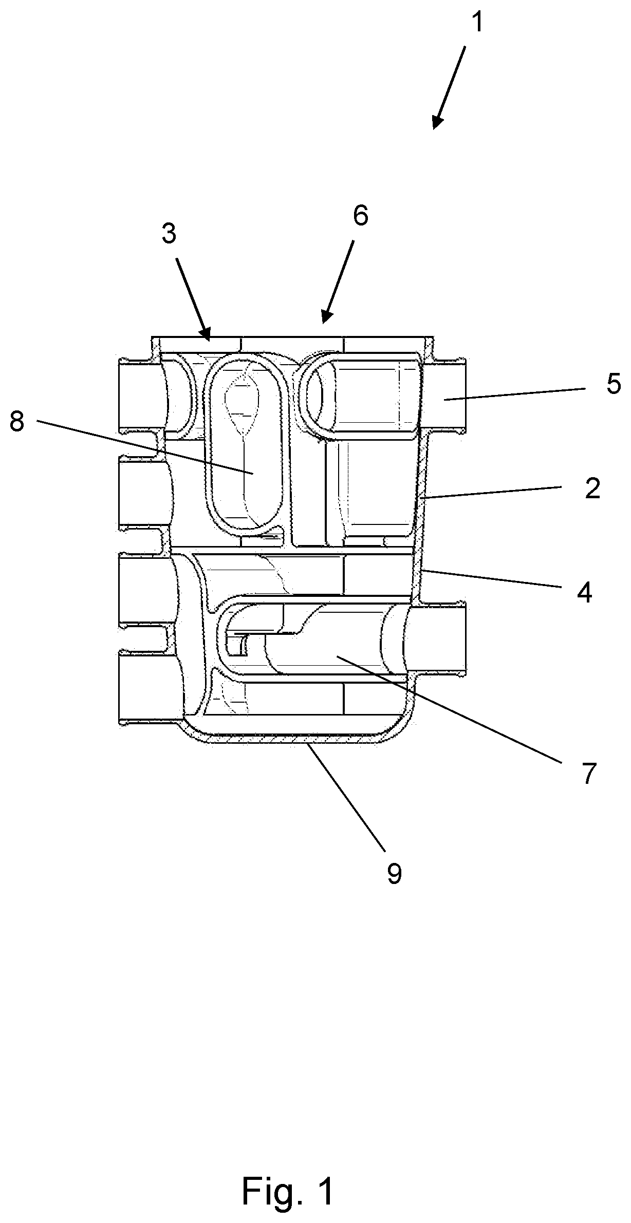
[0046]FIG. 1 shows a sectional view of the rotary valve 1 according to a From FIG. 1, it can be seen that the valve chamber 3 is formed in a conical shape. The valve core 7 is congruent with the valve chamber 3 on the outer circumference side and is thus also conical in shape. The valve chamber 3 is delimited by the chamber wall 4 and a chamber bottom 9. The chamber wall 4 surrounds the valve core 7, wherein the diameter of the chamber wall 4 widens, starting from the chamber bottom 9, in the direction of the receiving opening 6. To adjust the valve core 7 and to rotate the channel structure 8 relative to the fluid openings 5, the valve core can be moved both translationally and rotationally relative to the valve housing 2. In this case, an actuator can be brought into engagement with the valve core 7, which performs a superimposed rotational and translational movement. The translational movement creates a gap between the valve housing 2 and the valve core 7, which allows the valve...

second embodiment

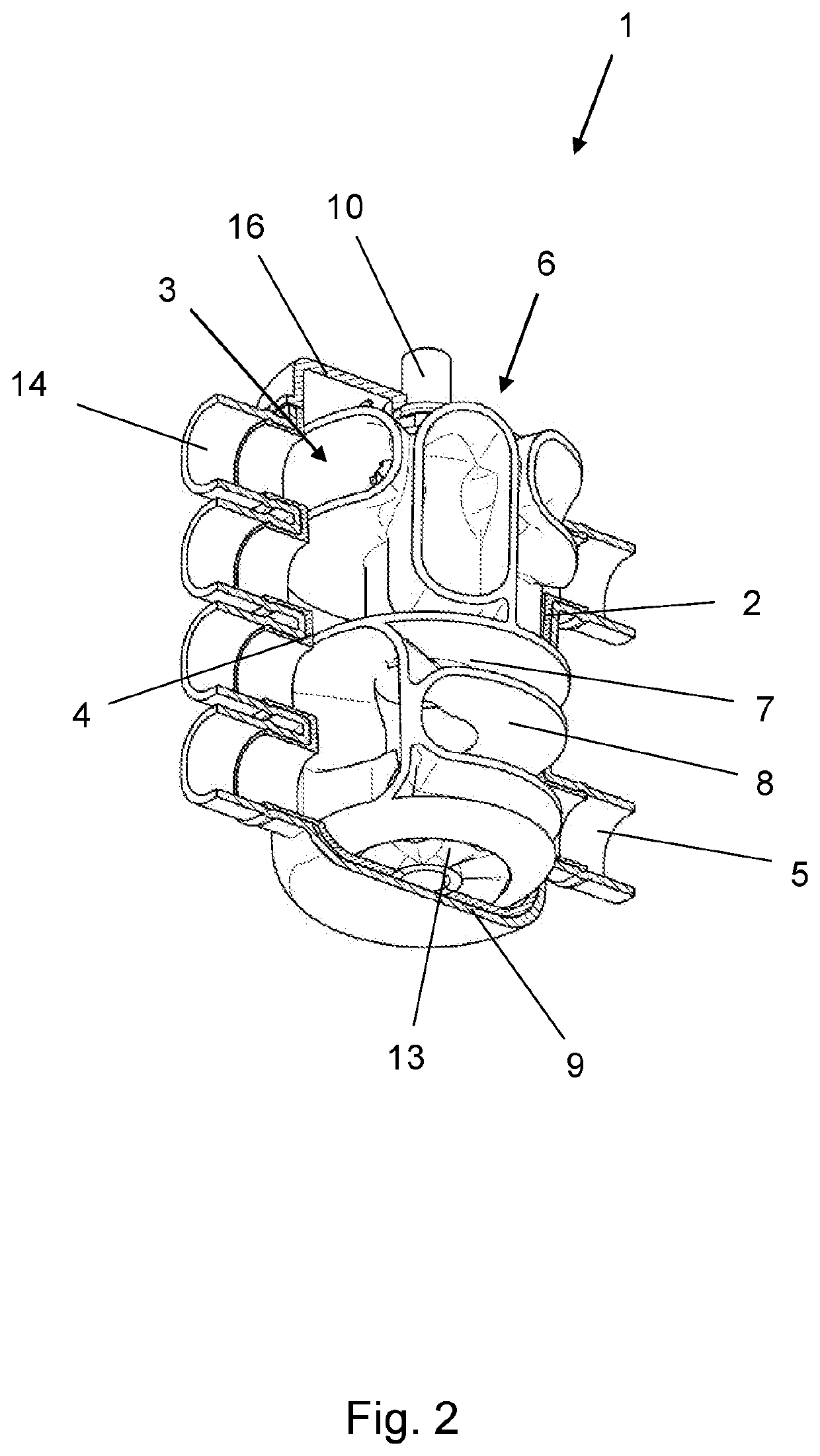
[0047]FIG. 2 shows a sectional view of the rotary valve 1 according to a In the design according to FIG. 2, the valve chamber 3 is also formed in a conical shape. The valve core 7 is congruent with the valve chamber 3 on the outer circumference side and is thus also conical in shape. The valve chamber 3 is delimited by the chamber wall 4 and a chamber bottom 9. The chamber wall 4 surrounds the valve core 7, wherein the diameter of the chamber wall 4 widens, starting from the chamber bottom 9, in the direction of the receiving opening 6.

[0048]The valve core 7 is supported both rotationally and translationally in the valve chamber 3. To adjust the valve core 7 and to rotate the channel structure 8 relative to the fluid openings 5, the valve core can be moved both translationally and rotationally relative to the valve housing 2.

[0049]In the present embodiment, however, only one actuator is required, which merely executes a rotational movement. To ensure that the valve core 7 simultane...

third embodiment

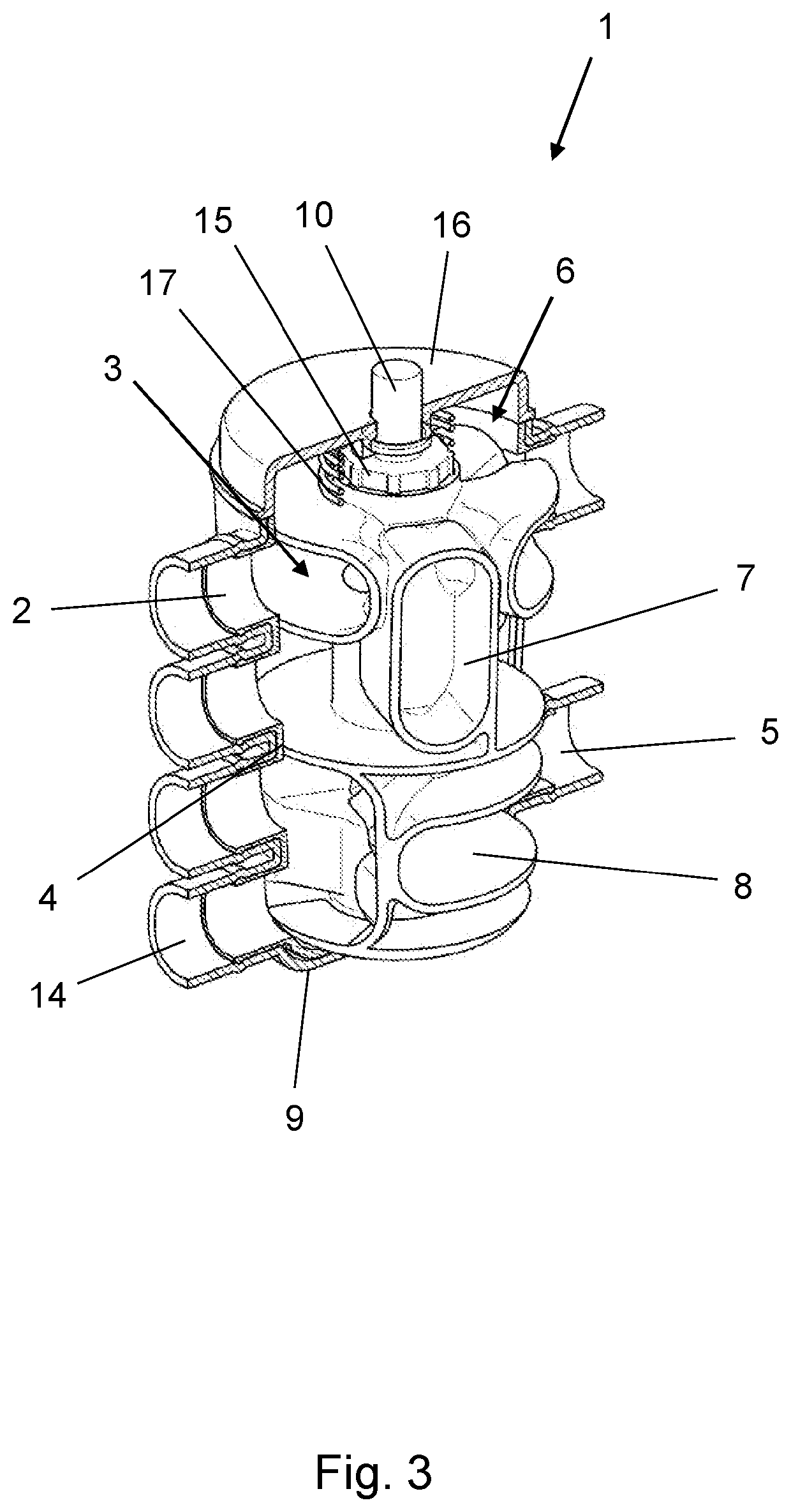
[0053]FIG. 6 shows a sectional view of the rotary valve 1 according to a In the design according to FIG. 6, the valve chamber 3 is also formed in a conical shape. The valve core 7 is congruent with the valve chamber 3 on the outer circumference side and is thus also conical in shape. The valve chamber 3 is delimited by the chamber wall 4 and a chamber bottom 9. The chamber wall 4 surrounds the valve core 7, wherein the diameter of the chamber wall 4 widens, starting from the chamber bottom 9, in the direction of the receiving opening 6.

[0054]The valve core 7 is supported both rotationally and translationally in the valve chamber 3. To adjust the valve core 7 and to rotate the channel structure 8 relative to the fluid openings 5, the valve core can be moved both translationally and rotationally relative to the valve housing 2.

[0055]In the present embodiment, however, only one actuator is required, which only executes a translational movement.

[0056]A bore extending in the axial direc...


PUM


Abstract

A rotary valve, comprising a valve housing with a valve chamber, wherein the valve chamber has a chamber wall in which at least two fluid openings are provided, wherein the valve chamber has a receiving opening on the end face side, wherein the valve chamber accommodates a valve core, wherein the valve core is provided with a channel structure which interacts with the fluid openings, wherein the valve core is supported in the valve chamber in a rotationally movable manner, wherein the valve chamber is formed in a conical shape.

Description

RELATED APPLICATIONS[0001]The present disclosure is a national phase application of European Application 20211671.1, filed on Dec. 3, 2020, the entire contents of each of which are incorporated herein by reference.FIELD[0002]The present disclosure relates to a rotary valve, comprising a valve housing with a valve chamber, wherein the valve chamber has a circumferential wall in which at least two fluid openings are provided, wherein the valve chamber has a receiving opening on the end face side, wherein the valve chamber receives a valve core, wherein the valve core is provided with a channel structure which interacts with the fluid openings, wherein the valve core is supported in the valve chamber in a rotationally movable manner.BACKGROUND[0003]Such a rotary valve is known, for example, from DE 10 2018 009 680 A1. Rotary valves of the type mentioned are often used in cooling circuits to control the flow of coolant. A cooling fluid can flow in and out through the fluid openings prov...

Claims


Application Information

Patent Timeline
IPC IPC(8): F16K11/083F16K27/06F28F27/02
CPCF16K11/0833F16K11/078F28F27/02F16K27/062F16K11/0853F16K5/0407F16K5/08F16K27/065F16K5/0242F16K5/0207F16K5/16F16K11/076F16K11/0836F16K27/045F16K11/072F16K11/083F16K25/005F16K31/002
Inventor BOECKER, ALBERTWINTER, MATTHIASSCHAEFER, THORSTENDEIBEL, FLORIANOLBRICH, MATTHIAS B.
Owner TI AUTOMOTIVE TECH CENT
Why Eureka
Try Eureka