Method and apparatus for performing measurements and monitoring of an object
- Summary
- Abstract
- Description
- Claims
- Application Information
AI Technical Summary
Benefits of technology
Problems solved by technology
Method used
Image

Examples
first embodiment
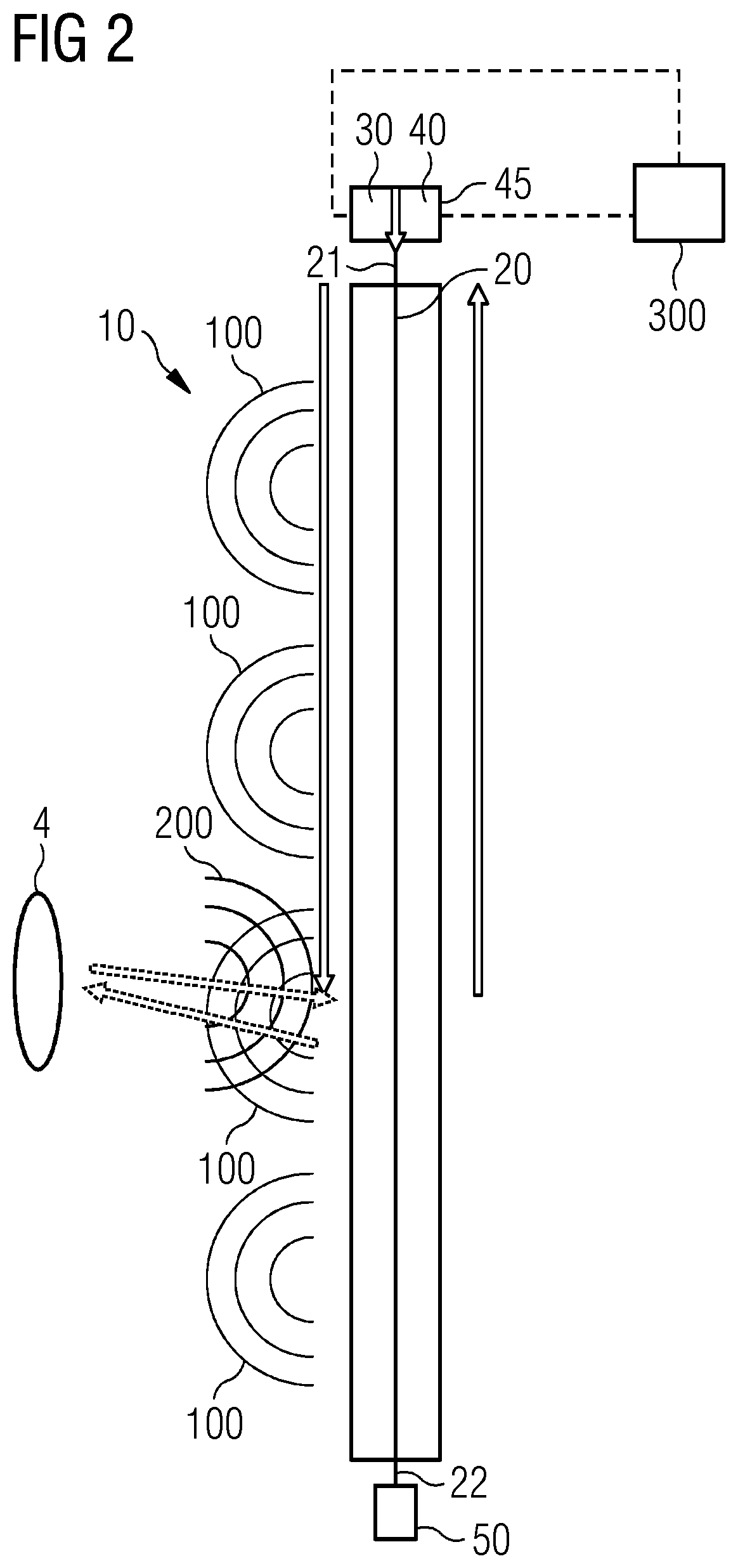
[0046]As shown in FIG. 2, the measurement and monitoring device 10 comprises only one leaky feeder 20. The leaky feeder 20 extends between a first end 21 and a second end 22. The first end 21 is connected to an electromagnetic transceiver 45 comprising one electromagnetic transmitter 30 and one electromagnetic receiver 40. The second end 22 is connected to one final resistance 50. The measurement and monitoring device 10 is used for detecting properties of at least a rotational blade 4 of the wind turbine 1. According to embodiments of the present invention, each rotational blade 4 of the wind turbine 1 can be monitored separately.
[0047]According to embodiments of the present invention, the electromagnetic transmitter 30 and the electromagnetic receiver 40 may be both connected to the first end 21 or to the second end 22 via a signal splitter or y-adapter. According to other embodiments of the present invention, the electromagnetic transmitter 30 is connected to the first end 21 and...
second embodiment
[0050]According to other embodiments of the present invention, a plurality of leaky feeders 20 may be used. As shown in FIG. 4, the measurement and monitoring device 10 comprises two leaky feeders 20, parallel to each other, and extending between respective first ends 21 and second ends 22, respectively adjacent to each other. The two leaky feeders 20 are configured according to an antiparallel configuration, where a first leaky feeder 20 extends between:[0051]an electromagnetic transmitter 30 connected to the first end 21, and[0052]a final resistance 50 connected to the second end 22;
while a second leaky feeder 20 extends between:[0053]a final resistance 50 connected to the first end 21, and[0054]an electromagnetic receiver 40 connected to the second end 22.
[0055]In such embodiment, one first leaky feeder 20, connected to the electromagnetic transmitter 30, is dedicated for the transmission of the first electromagnetic signal 100, while another second leaky feeder 20, connected to ...
fourth embodiment
[0069]FIG. 8 shows a measurement and monitoring device 10 not used in a wind turbine. Such embodiment comprises an arrangement of two leaky feeders 20 in an anti-parallel configuration, like that of the embodiment of FIG. 4. The two leaky feeders 20 are arranged on an annular support 11 and forming two complete concentric circles covering approximately 360 degrees on a plane. The leaky feeder 20 connected to the transmitter 30 is arranged on the annular support 11 in a circle having a smaller diameter than the circle formed by the leaky feeder 20 connected to the receiver 40. The measurement and monitoring device 10 of the present embodiment may be used for analysing an object 12 moving towards and / or through the circles formed by the leaky feeders 20. Alternatively, according to other embodiments of the present invention (not shown), the same purpose could be achieved by arranging only one leaky feeder 20 on the support 11, shaped in one circle covering approximately 360 degrees on...
PUM
 Abstract
Description
Claims
Application Information
 - R&D Engineer
- R&D Manager
- IP Professional
- Industry Leading Data Capabilities
- Powerful AI technology
- Patent DNA Extraction
Browse by: Latest US Patents, China's latest patents, Technical Efficacy Thesaurus, Application Domain, Technology Topic.
© 2024 PatSnap. All rights reserved.Legal|Privacy policy|Modern Slavery Act Transparency Statement|Sitemap