
Chair, pressing device

a pressing device and chair technology, applied in the field of chairs, can solve the problems of shortened front thigh and buttock muscles, damage to the spine, hip and knee joints, and increased pain in the back of the thigh and buttocks, and achieve the effects of simple and safe application, convenient and simplified application, and improved comfor

Pending Publication Date: 2022-06-16
BEHRENDT CHRISTIAN
View PDF0 Cites 4 Cited by
  • Summary
  • Abstract
  • Description
  • Claims
  • Application Information

AI Technical Summary

Benefits of technology

The invention provides a chair that helps to stretch muscles in the hip and legs, while also making it easier to apply pressure to those areas. This is achieved by attaching a pressing device to a chair, which allows the pressure to be applied at specific locations on the person's body. By using this chair with the attached pressing device, a person can stretch their muscles more efficiently and without having to manually apply pressure. Additionally, the chair allows for self-therapy and enables the person to perform other activities while the pressing device is in use. The position of the pressure elements can also be adjusted, and a control system simplifies the application and makes it safer and more reliable.

Problems solved by technology

Frequent sitting causes shortening of the front and back thigh and front hip muscles and the calf, with resulting damage to the spine, hip, and knee joint, as well as pressure sores can develop on the back of the thigh and buttocks, and other undesirable phenomena.
Especially for people who sit a lot on conventional chairs, the problem is that the front thigh and hip muscles often shorten and the spine is loaded unfavorably.
It is also known that tissue becomes hyperelastic when pressure is applied to these cells.
A disadvantage of such a therapy method is the high personnel effort and the requirement to go to a therapist or to have a therapist come, since a self-therapy is difficult or not possible at all.

Method used


Image

  • Chair, pressing device
  • Chair, pressing device
  • Chair, pressing device

Examples


Embodiment Construction

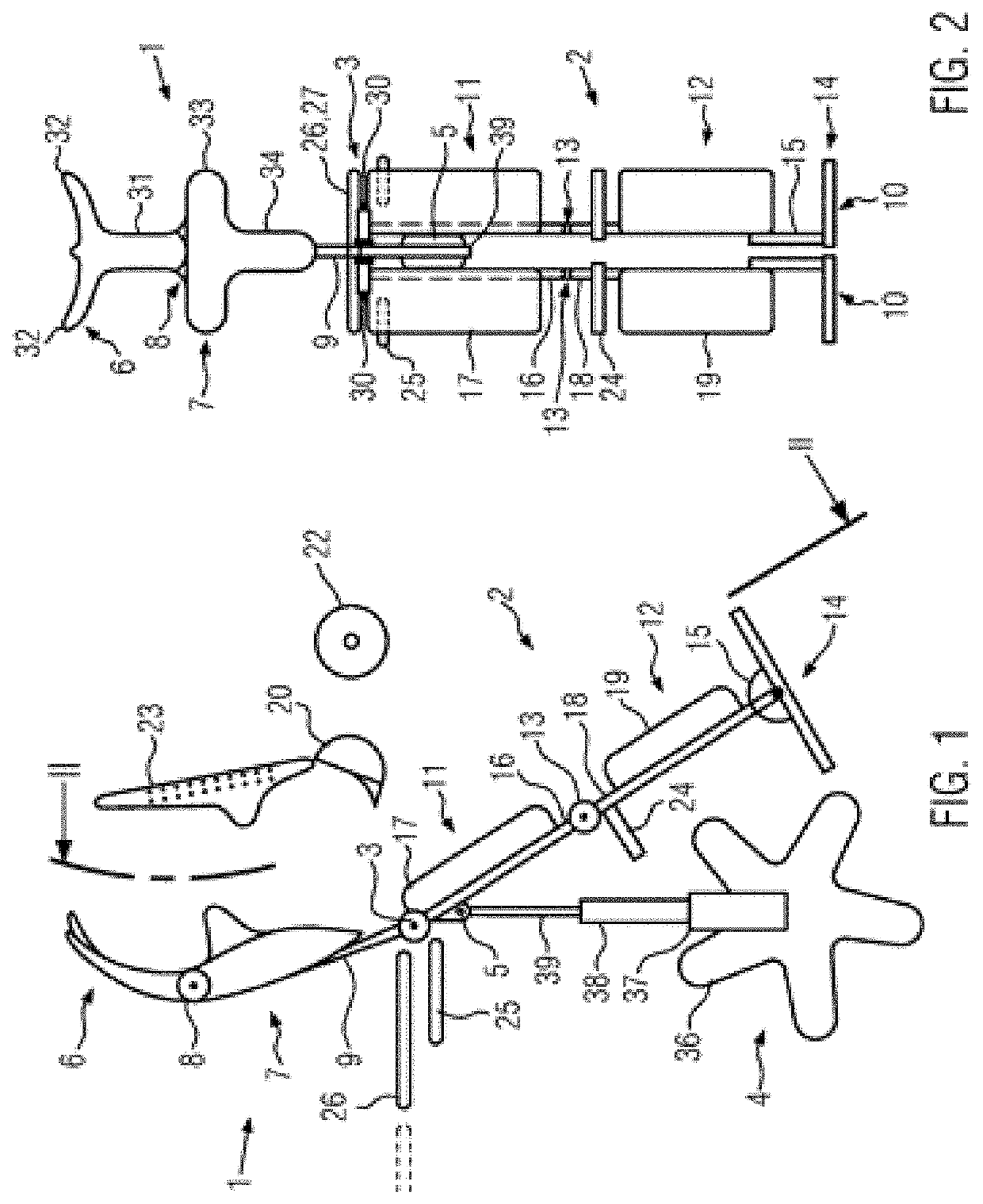
[0090]All graphic representations are to be understood schematically. Directional and positional designations are used in accordance with the usual anatomical names and, unless otherwise indicated, refer to a body placed on the chair in the prone position. A longitudinal direction is basically understood as a direction running along the stretched spine or between the atlas and sacrum of the body placed in prone position on the chair according to the invention. However, a longitudinal direction can also be understood as a local directional indication of a direction that runs approximately through line II-II in FIG. 1 in the drawing plane. A transverse direction is understood to be a direction that runs through both hip joints or both shoulder joints of the body in prone position on the chair according to the invention and is perpendicular to the drawing plane in FIG. 1. A sagittal direction is understood to be a direction perpendicular to the longitudinal direction and the transverse...


PUM


Abstract

The invention relates to a chair for accommodating a person. The chair includesan upper body section having an upper body contact surface adapted or adaptable to at least parts of a front of a torso or a rear of a torso of a person placed on the chair, anda lower body section having a lower body contact surface adapted or adaptable to at least parts of at least a front of a thigh of the person, wherein the upper body section and the lower body section are arranged or arrangeable and fixable in a position relative to each other such that the upper body contact surface and the lower body contact surface cause a hyperextension posture of the hip joint of the person with a predetermined hyperextension angle. By forming the hyperextension angle of the hip on the chair, shortening of the anterior thigh and hip muscles can be counteracted. Also disclosed are a pressing device for application to the human body, which is adapted for use on a chair and which includes one or more pressure units each having at least one pressure head adapted to apply local or point pressure at a predetermined pressure location on the body of a person accommodated on the chair, and a chair having such a pressing device.

Description

BACKGROUND OF THE INVENTION[0001]The present invention relates to a chair for accommodating a person and to a pressing device for applying a local or punctual pressure at one or more pressure locations on the human body.[0002]Chairs are conventionally designed to accommodate a human body in a seated position with a back resting against a backrest and the backs of the thighs resting on a seat surface, with the upper body and thighs forming an angle of slightly more or less than 90°. Frequent sitting causes shortening of the front and back thigh and front hip muscles and the calf, with resulting damage to the spine, hip, and knee joint, as well as pressure sores can develop on the back of the thigh and buttocks, and other undesirable phenomena.[0003]In order to at least reduce the strain on the spine, it is known to use chairs whose backrests are connected to the seat by a narrower connecting part in such a way that a person sits astride the chair and leans against the backrest with t...

Claims


Application Information

Patent Timeline
Patent Type & Authority Applications(United States)
IPC IPC(8): A61H1/02A61H39/04
CPCA61H1/0244A61H2203/0468A61H1/0296A61H1/024A61H39/04A61H2201/0134A61H2201/0149A61H2201/0192A61H2201/1284A61H2201/1676A61H2201/1685A61H2201/1695A61H2201/5053A61H2201/5061A61H2203/0431A61H1/0266A47C9/005A47C7/024A47C7/383A47C7/405A47C7/503A47C7/5066A47C9/025A47C1/024A61H23/02A61H2205/082A61H2201/0138A61H2201/1604A61H2205/04A61H2201/164A61H2201/1623A61H1/0222A61H2201/1261A61H2205/088A61H2205/081A61H1/0292A61H2201/0173A61H2201/5043A61H2201/1633
Inventor BEHRENDT, CHRISTIAN
Owner BEHRENDT CHRISTIAN
Learn More