LED lighting bulb and manufactring method

Active Publication Date: 2022-06-16
SIGNIFY HOLDING B V
View PDF0 Cites 0 Cited by
  • Summary
  • Abstract
  • Description
  • Claims
  • Application Information

AI Technical Summary

Benefits of technology

[0020]This bulb has a lighting driver on the envelope side of the stem portion of the end cap, i.e. within the bulb envelope. To protect the lighting driver during assembly, for example during sintering of the envelope to the stem portion (to seal the envelope), the lighting driver is slideable along the first and second wires. This means the assembly can take place with the lighting driver remote from the stem portion, and after assembly, the lighting driver can be pulled back to the stem portion using the first and second supply wires. Thus, during assembly the lighting driver is able to slide along (or over or between) the first wire and the second wire. The lighting driver can be positioned within the interior volume of the envelope, and does not need to be confined to an internal volume of the end cap.
[0021]By pulling the driver back the to stem portion, it is moved out

Problems solved by technology

However, this places a limitation on the possible size of the lighting driver.
This detracts from the aesthetic appearance of the bulb and also adds to the overall size of the bulb which may not be desired.
However, t

Method used


Image

  • LED lighting bulb and manufactring method
  • LED lighting bulb and manufactring method
  • LED lighting bulb and manufactring method

Examples


Example

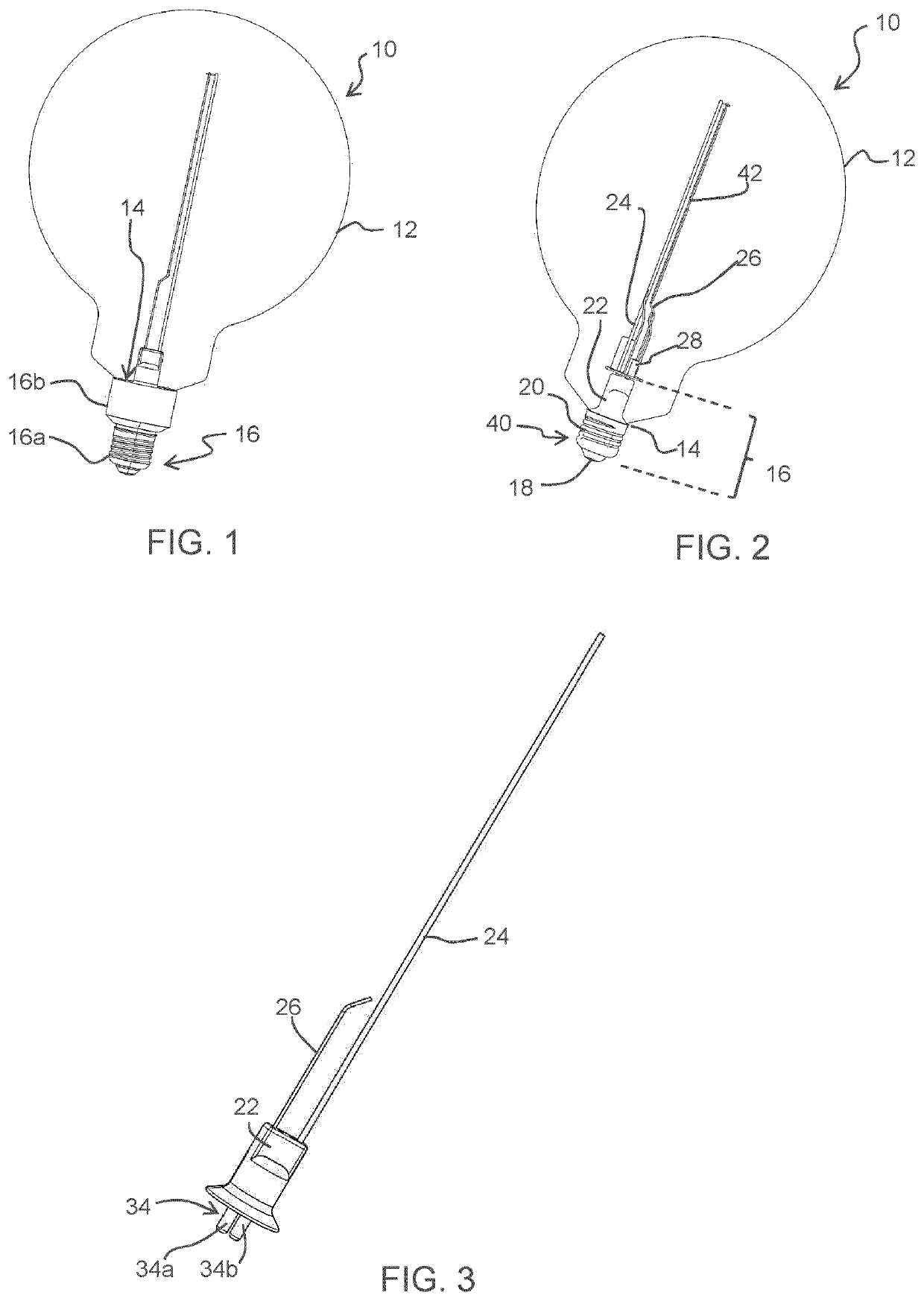
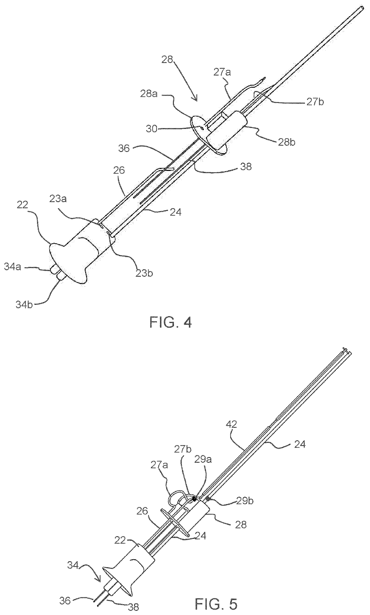
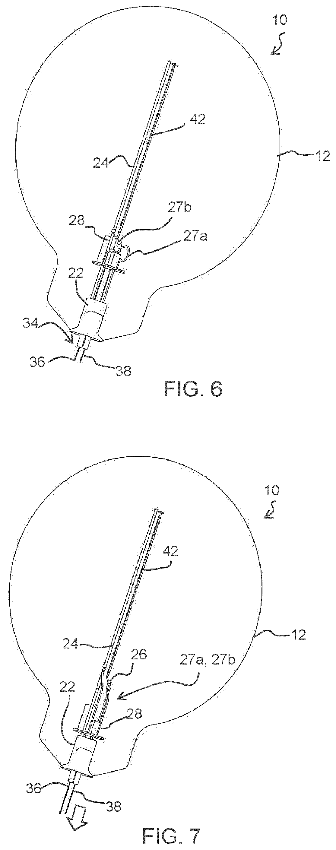
[0063]The invention will be described with reference to the Figures.

[0064]It should be understood that the detailed description and specific examples, while indicating exemplary embodiments of the apparatus, systems and methods, are intended for purposes of illustration only and are not intended to limit the scope of the invention. These and other features, aspects, and advantages of the apparatus, systems and methods of the present invention will become better understood from the following description, appended claims, and accompanying drawings. It should be understood that the Figures are merely schematic and are not drawn to scale. It should also be understood that the same reference numerals are used throughout the Figures to indicate the same or similar parts.

[0065]The invention provides a LED lighting bulb in which a lighting driver is located within the bulb envelope. During assembly, the lighting driver may be positioned away from an opening of the envelope so that high temp...


PUM


Abstract

A LED lighting bulb (10) has a lighting driver (28) which is located within the bulb envelope (12). During assembly, the lighting driver (28) may be positioned away from an opening (14) of the envelope (12) so that high temperature sealing of a stem portion (22) of the end cap (16) to the envelope opening (12) can take place. The lighting driver (28) can then be pulled into position against the stem portion (22), and assembly of the end cap (16) can then be completed.

Description

FIELD OF THE INVENTION[0001]This invention relates to a LED lighting bulb and manufacturing method, and in particular to a bulb which incorporates a lighting driver.BACKGROUND OF THE INVENTION[0002]A LED lighting bulb, in particular which is able to be driven by mains power, requires a lighting driver circuit to be incorporated into the bulb. The lighting driver may for example be a switch mode power converter or other type of driver circuit.[0003]A LED lighting bulb typically comprises a glass envelope and an end cap which closes an opening in the glass envelope and defines the external terminal contacts of the bulb. The end cap may be an Edison screw fitting (e.g. E17 or E27) or a bayonet cap (e.g. B15 or B22) or a pin connector (e.g. MR16). The end cap is located outside the envelope and for example has (or is attached to) a stem which seals the opening in the envelope.[0004]The known approach is to position the lighting driver in the end cap. The stem of the end cap can be seale...

Claims


Application Information

Patent Timeline
IPC IPC(8): F21K9/232F21K9/238F21K9/90
CPCF21K9/232F21K9/90F21K9/238F21V23/002
Inventor YAN, CHENGRUIZOU, RUISHEN, MORNA
Owner SIGNIFY HOLDING B V
Why Eureka
Try Eureka