Sensor system for vehicle tyres and vehicle tyres

A technology of sensors and wear sensors, which is applied in the field of sensor systems and can solve problems such as tearing

Inactive Publication Date: 2021-12-07
CONTINENTAL REIFEN DEUTSCHLAND GMBH
View PDF1 Cites 0 Cited by
  • Summary
  • Abstract
  • Description
  • Claims
  • Application Information

AI Technical Summary

Problems solved by technology

However, especially in solid rubber tyres, these wires or metal conductor strips are exposed to strong deformation forces and thus may tear under long-term stress

Method used


Image

  • Sensor system for vehicle tyres and vehicle tyres
  • Sensor system for vehicle tyres and vehicle tyres
  • Sensor system for vehicle tyres and vehicle tyres

Examples


Embodiment Construction

[0058] figure 1 A vehicle tire 1 is shown which is in the form of a solid rubber tire and is arranged on a rim 5 of a wheel system. The vehicle tire 1 has various elastomer layers. However, use in pneumatic tires is also conceivable. In a known manner, the elastomer layers form the bottom layer 4 with steel bars 6 , the intermediate layer 3 and the running layer 2 , each layer having different properties. In particular, the intermediate layer 3 is designed to be relatively elastic in order to minimize rolling resistance and thus reduce heat generation.

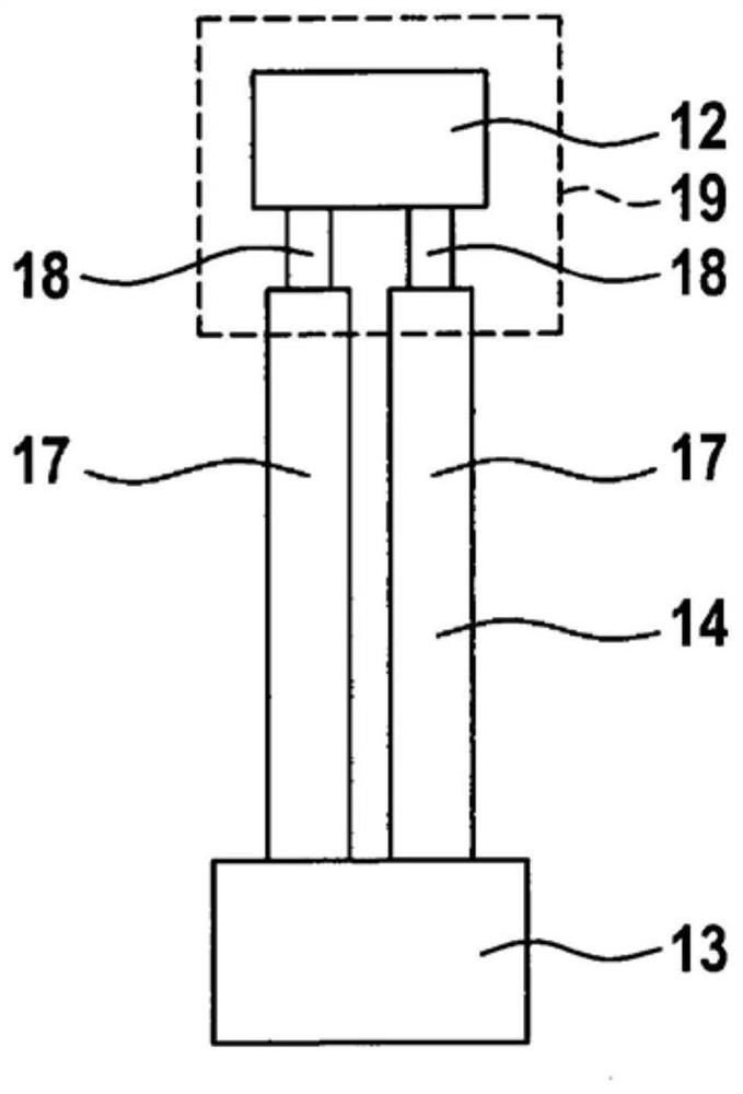
[0059] A vehicle tire 1 has in a hole (not shown) a sensor system 10 with a first sensor 11 and a second sensor 12 and a control unit 13 which in the illustrated embodiment is in the form of a microcontroller and arranged or Fastened in the region of the rim 5, for example in a molded-in recess.

[0060] The sensor 11 is arranged in the operating layer 2 and is in the form of a wear sensor. The area 27 of the sensor 11 fo...


PUM


Abstract

The invention relates to a sensor system (10) for vehicle tyres (1) comprising at least one sensor (11, 12) and at least one control unit (13), wherein the sensor (11, 12) is electrically connected to the control unit (13) by means of at least one conductor path consisting of electrically conductive elastomers.

Description

technical field [0001] The invention relates to a sensor system for vehicle tires. The invention also relates to a vehicle tire, in particular a solid rubber tire, provided with such a sensor system. Background technique [0002] WO 2018 / 077502 A1 discloses the practice of using sensor elements in solid rubber tires. The problem here is the connection between the individual sensor elements and the control unit (for example a microcontroller) assigned to the sensor elements. [0003] This connection is typically via wires or metal conductor strips. However, especially in solid rubber tyres, these wires or metal conductor strips are exposed to strong deforming forces and thus may tear under long-term stress. It is especially important that the sensor element is not intended to be arranged in the region of the rim, and thus not in the vicinity of the control unit, but rather further outside in the tire. Contents of the invention [0004] The object of the present inventio...

Claims


Application Information

Patent Timeline
Patent Type & Authority Applications(China)
IPC IPC(8): B60C11/24B60C23/20
CPCB60C11/243B60C23/20B60C2019/004B60C19/00
Inventor 汉斯-尤尔根·索尔沃德马蒂亚斯·索尔沃德
Owner CONTINENTAL REIFEN DEUTSCHLAND GMBH
Why Eureka
Try Eureka