
Central vacuum system mounting flange and hose cuff for use with standard electrical outlets

a technology of central vacuum system and mounting flange, which is applied in the direction of connection contact material, insulated conductor, cable, etc., can solve the problems of inconvenient two-way connection, inconvenient installation, and inability to meet the needs of two-way connections, so as to reduce the cost of installing and maintaining the electrical inlet valve, the effect of increasing the installation directness and reducing the cos

Inactive Publication Date: 2008-12-18
PLASTIFLEX GRP NV
View PDF11 Cites 0 Cited by
  • Summary
  • Abstract
  • Description
  • Claims
  • Application Information

AI Technical Summary

Benefits of technology

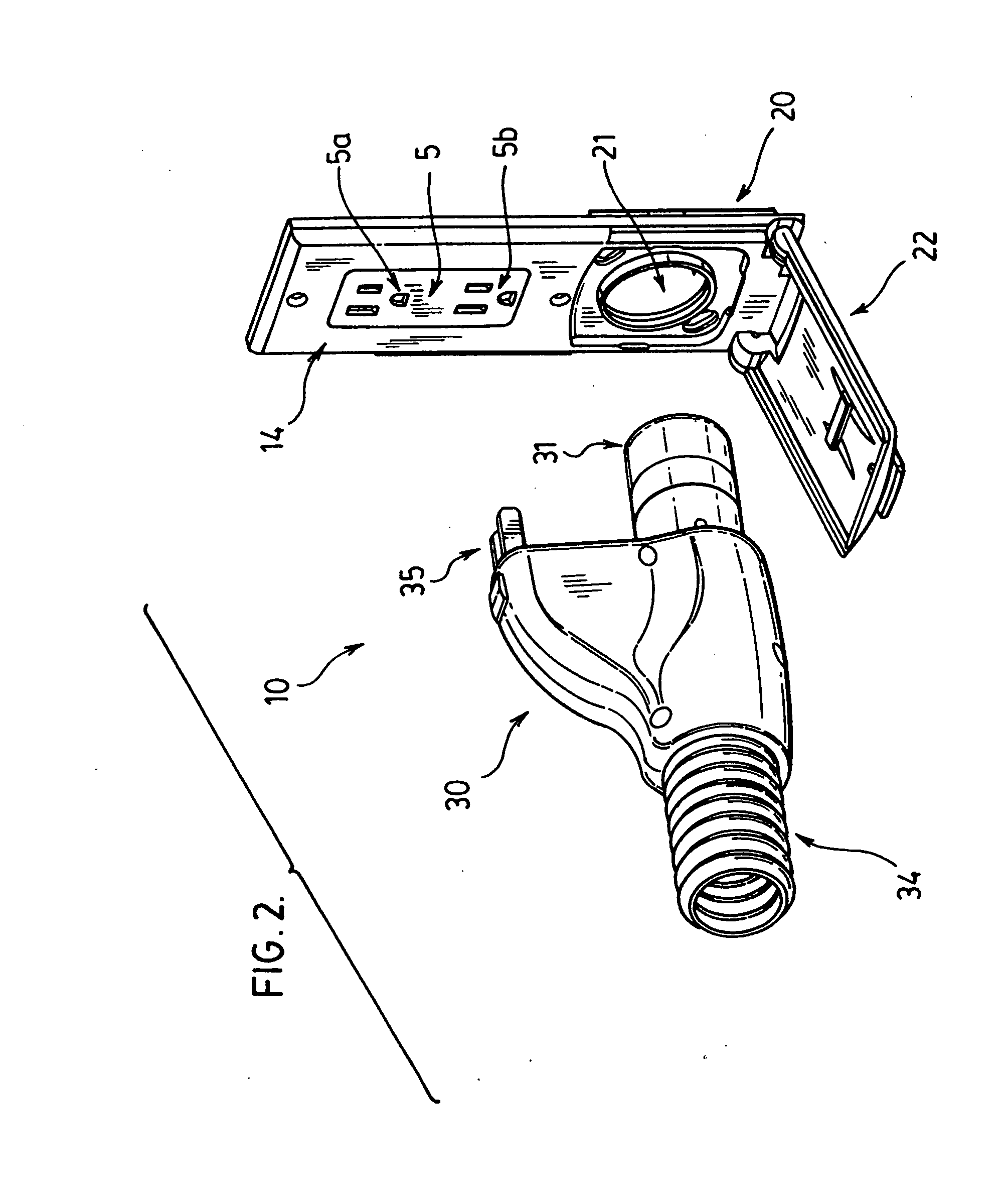
[0013]Accordingly, in one preferred embodiment, an advantage of the present invention is that a direct connect hose cuff having standard electrical terminals can be used to provide a high voltage connection to an attachment for a current carrying flexible hose. This occurs, at least in part, because the hose cuff has standard electrical terminals which can engage into an electrical plug of an electrical receptacle, providing a more robust electrical connection.
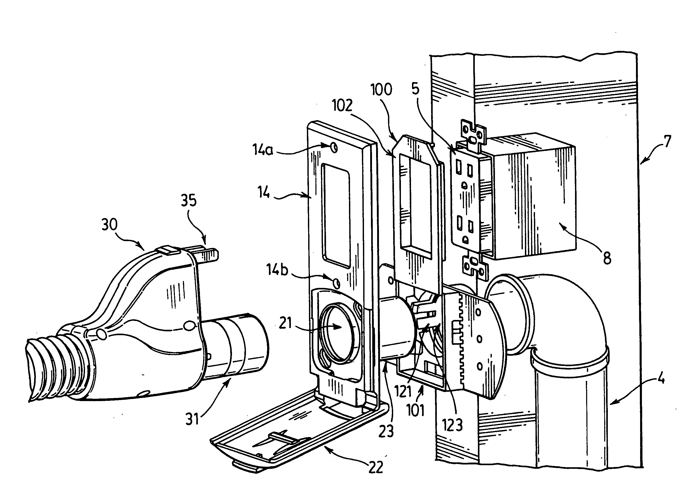
[0014]In a further embodiment, additional advantages involve more direct installation. This arises, at least in part, by avoiding the need for a separate visit by an electrician. In one preferred embodiment, the vacuum hose connection in the inlet valve is installed at a known orientation with respect to the electrical receptacle. This is done even though the electrical receptacle is not installed generally at the time the vacuum system is installed by using the fact that all electrical receptacles have a standard distance with respect to the other components of the electrical box. In a preferred embodiment, a mounting flange is used to orient the vacuum connection opening with respect to the securing holes which are used during installation of the actual electrical receptacle. In this way, the vacuum hose connection may be oriented in a first known orientation with respect to the anticipated orientation of the electrical connection when it is eventually inserted into the electrical box. In one preferred embodiment, this provides for the vacuum system to be roughed in without the need for an electrician to make a separate electrical connection for a high voltage connection associated with the vacuum system at least in part because the inlet valve would be set in a known orientation with respect to the electrical receptacle, which known orientation corresponds to the orientation of the electrical terminals and vacuum connection of the hose cuff.
[0015]Furthermore, in a preferred embodiment, the orienting portion used on the mounting flange for orienting the vacuum connection opening with respect to the anticipated orientation of the electrical receptacle is removable. This can be done in one preferred embodiment, for instance, by having a frangible portion which permits the orienting portion to be removed from the main body. In this way, once the main body of the mounting plate having the vacuum connection opening is secured in the appropriate orientation with respect to the anticipated position of the electrical receptacle, the orienting portion can be removed thereby avoiding any interference with the other trades, such as the electrician.
[0016]A further advantage of at least one embodiment of the present invention is that no additional wall valve electrical wiring is required. In other words, the inlet valve as installed does not contain any high voltage electrical wiring. This decreases the costs associated with the inlet valve. This further decreases the cost of installing and maintaining the electrical inlet valve. For instance, long term difficulties regarding wiring can be decreased as all high voltage power emanates from a standard electrical box. Furthermore, because a standard electrical box is used without any interference between the inlet valve and the electrical box, this invention can be easily adapted for use in non-custom built homes.
[0017]In a further preferred embodiment, the hose cuff used to mate with the electrical receptacle and the inlet valve is arranged such that the vacuum connection is located below the electrical receptacle. This is done for a number of reasons. First, the location of the electrical receptacle to the structural element is variable, either on the left or right side of the stud. Thus, if the electrical receptacle was located on the same plane as the vacuum inlet valve, it would be necessary to have a left hose cuff connection and a right hose cuff connection because of the fact that the structural element would increase and vary the distance between the electrical receptacle and vacuum inlet valve and would prevent the hose cuff from being interchangeable between the vacuum inlet valve on the left side and a vacuum inlet valve on the right side of the electrical receptacle. Furthermore, by having the electrical terminals above the vacuum inlet valve, it is easier for the consumer to insert the electrical terminals, which are generally smaller and more difficult to insert, into the electrical receptacle while simultaneously inserting the vacuum connection of the hose cuff into the vacuum connection opening of the inlet valve. This is the case at least because the user will be able to see the electrical terminals, which are on top, contrary to the case if the electrical terminals were below the vacuum connection. Furthermore, the electrical terminals have a space between them and are shorter than the vacuum connection of the hose cuff which permits the user to view the vacuum connection of the hose cuff while at the same time viewing the electrical terminals. Clearly, this would not be the case if the vacuum connection was located above the electrical terminals.
[0018]In a further preferred embodiment, the electrical terminals may be rotatable from a first position where their lengthwise axis is substantially parallel to the center line of the vacuum connection, to a second position where the lengthwise axis is substantially perpendicular to the center axis of the vacuum connection. This could be done, for instance, to provide the same hose cuff to be used with vacuum inlet valves that have not been installed with an electrical receptacle oriented with respect to the vacuum connection opening of the inlet valve.

Problems solved by technology

However, it is generally less convenient if two separate connections are required, one for the high voltage source and another for the vacuum and low voltage connection.
The difficulty with these types of terminals or pins is that they are not robust and may be broken.
Any rotational movement can damage the pins thereby rendering the high voltage portion of the hose useless requiring replacement of the hose or use of the hose only without power being sent to any attachments.
However, these prior art devices generally require a licensed electrician to install the electrical power receptacle portion of the inlet valve which generally increases the cost of installation.
Clearly, the separate visit by the electrician results in additional costs.
Furthermore, there are additional costs in coordinating the attendance of the various trades at the correct time.

Method used


Image

  • Central vacuum system mounting flange and hose cuff for use with standard electrical outlets
  • Central vacuum system mounting flange and hose cuff for use with standard electrical outlets
  • Central vacuum system mounting flange and hose cuff for use with standard electrical outlets

Examples


Embodiment Construction

[0040]Preferred embodiments of the invention and its advantages can be understood by referring to the present drawings. In the present drawings, like numerals are used for like and corresponding parts of the accompanying drawings.

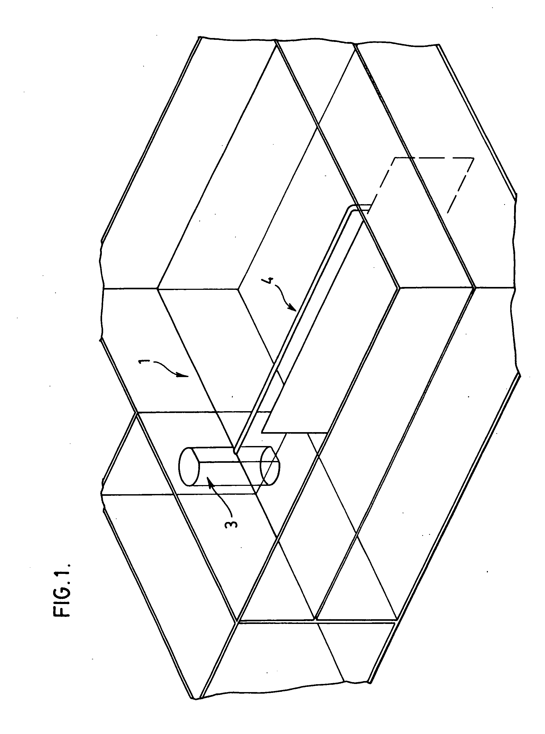
[0041]FIG. 1 symbolically illustrates one possible central vacuum system, shown generally by reference numeral 1, with which the present invention may be used. As shown in FIG. 1, the vacuum system 1 comprises a central vacuum source, shown generally by reference numeral 3, connected by way of pipes, shown generally by reference numeral 4, to at least one vacuum inlet valve. It is understood that the central vacuum system 1 may have several links of pipe 4 all leading to the same vacuum source 3. It is further understood that the vacuum system 1 may be installed in any type of structure, such as a house, apartment, residential condominium, commercial condominium unit or industrial unit. There is no substantial restriction on the location or structure where ...


PUM


Abstract

A mounting plate having an orienting portion facilitates orienting the vacuum connection opening of the mounting plate with respect to an anticipated orientation of a receptacle and electrical box. The orienting portion is optionally releasably attachable to the main body of the mounting plate which main body comprises the vacuum connection opening. The mounting plate is mounted prior to installation of the electrical receptacle in the electrical box. The orienting portion of the mounting plate facilitates orienting the vacuum connection opening in a known orientation with respect to an anticipated orientation of the electrical receptacle when inserted in the electrical box. After installation of the inlet valve and the electrical receptacle, a hose cuff having standard electrical terminals oriented with respect to the vacuum connection of the hose cuff may be simultaneously inserted into the electrical receptacle and the vacuum connection opening. The electrical terminals in the hose cuff are oriented with respect to the vacuum connection in a second known orientation corresponding to the first known orientation such that the electrical terminals mate with the electrical receptacle which has been installed in the electrical box when the vacuum connection opening receives the vacuum connection. In this manner, a hose cuff utilizing standard electrical terminals may be mated with an electrical terminal without interfering with the electrical box. Furthermore, because the orienting portion is releasably attached to the main body, the orienting portion can be removed to avoid interference with other trades.

Description

RELATED APPLICATIONS[0001]This is a continuation of U.S. application Ser. No. 11 / 168,844 filed Jun. 28, 2005 for the invention entitled “Central Vacuum System Mounting Flange and Hose Cuff for Use with Standard Electrical Outlets”.FIELD OF THE INVENTION[0002]This invention relates to inlet valves and inlet valve assemblies used in association with central vacuum cleaning systems. In particular, this invention relates to inlet valves and inlet valve assemblies, and a method for installing the inlet valves and inlet valve assemblies of the type that utilize both high voltage and low voltage wiring connections.BACKGROUND OF THE INVENTION[0003]In the past, there have been many different types of inlet valves and inlet valve assemblies. In general, all inlet valves have at least a low voltage connection. The low voltage connection provides for remote switching to activate the central vacuum source of the central vacuum system.[0004]Other types of central vacuum system also provide for a ...

Claims


Application Information

Patent Timeline
Patent Type & Authority Applications(United States)
IPC IPC(8): H01R4/60
CPCH01R13/005
Inventor SHEREMETA, JAMES GEORGEMIKA, DANIEL DAVID RICHARD
Owner PLASTIFLEX GRP NV
Learn More