Hand-turnable welding cable connection

Inactive Publication Date: 2014-12-04
ILLINOIS TOOL WORKS INC
View PDF6 Cites 0 Cited by
  • Summary
  • Abstract
  • Description
  • Claims
  • Application Information

AI Technical Summary

Benefits of technology

[0003]Disclosed is a hand-turnable welding cable connection for a replaceable welding cable that reduces the possibility of human error during installation. The welding cable connection provides a robust electrical connection and reduces the possibility

Problems solved by technology

However, this method of connecting the welding cable is cumbersome and can result in a loose connection between the welding cable and welding t

Method used


Image

  • Hand-turnable welding cable connection
  • Hand-turnable welding cable connection
  • Hand-turnable welding cable connection

Examples


Embodiment Construction

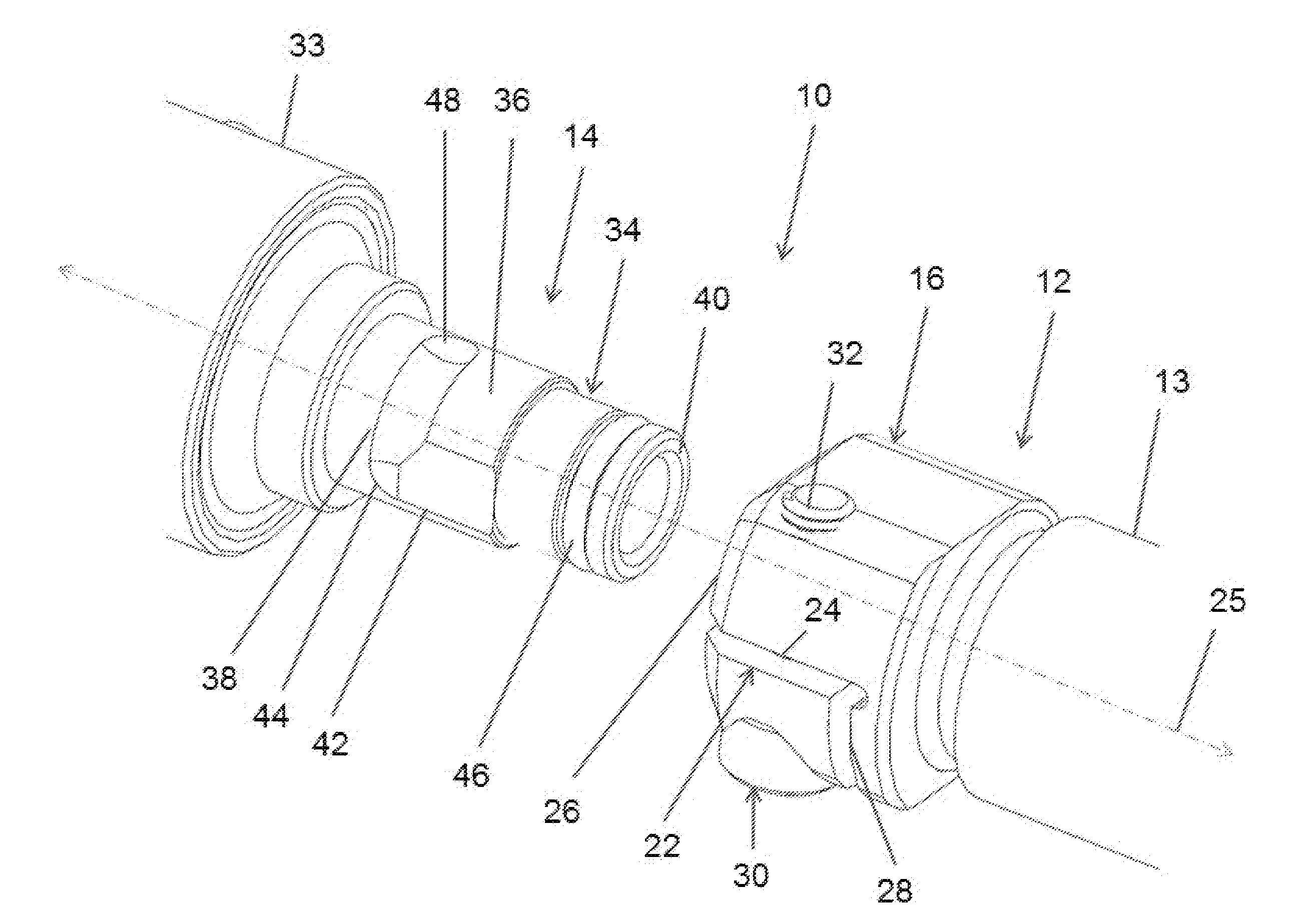
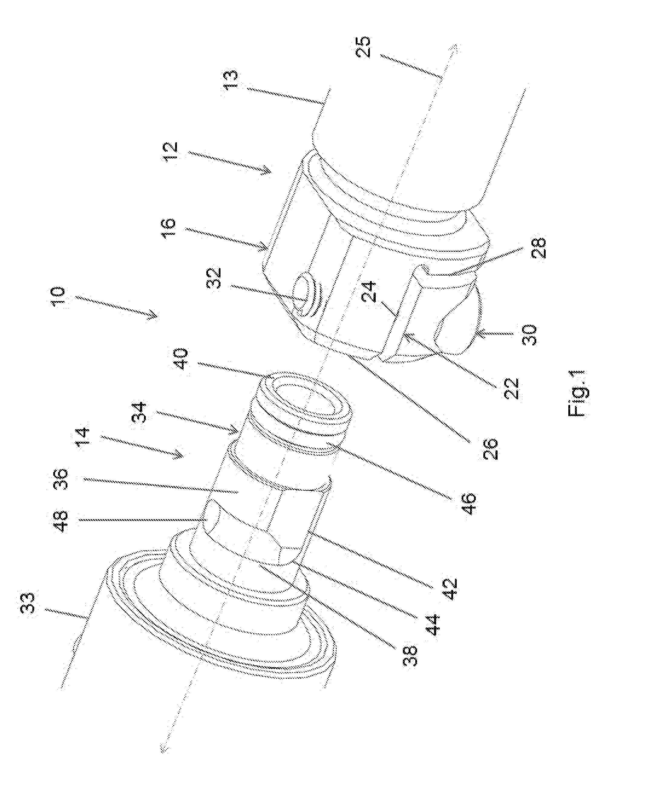
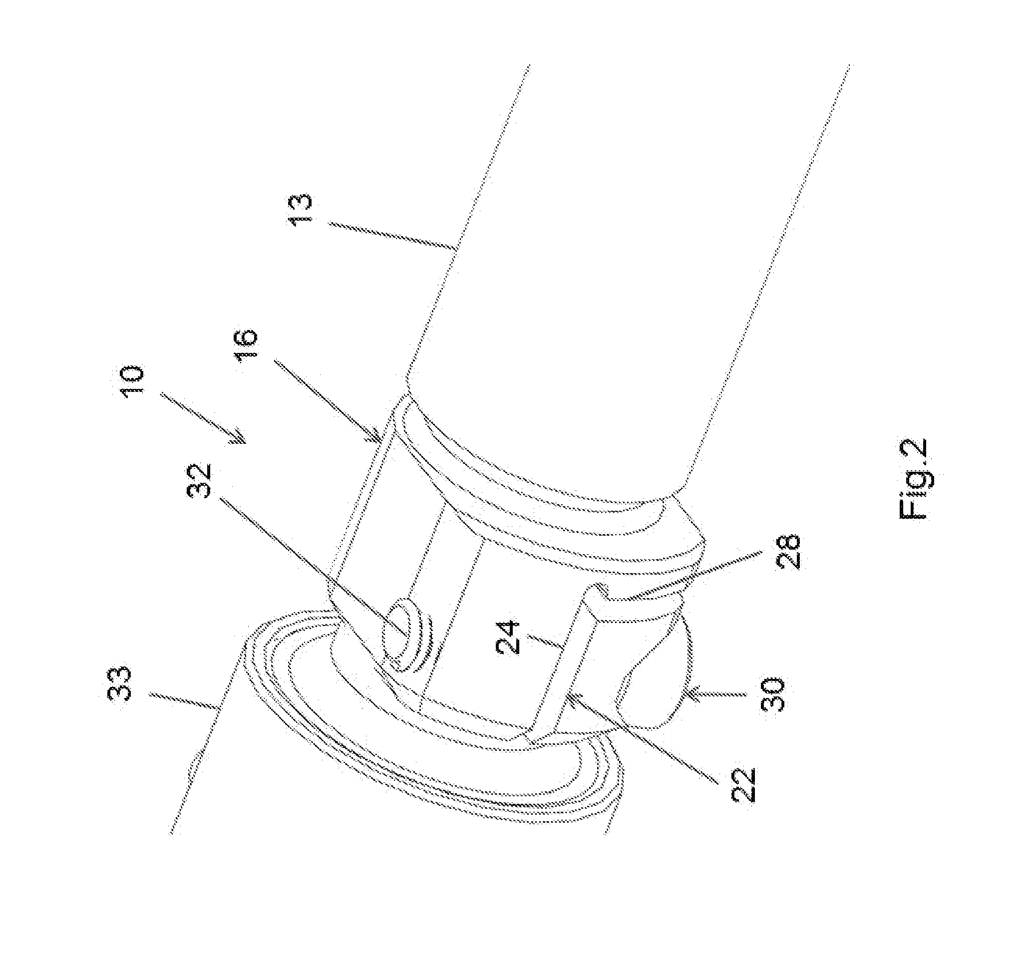
[0016]Referring to FIGS. 1 through 4 of the drawings in detail, numeral 10 generally indicates a hand-turnable welding cable connection. The hand-turnable welding cable connection 10 facilitates the connection of a welding cable to a welding torch and improves the seal between the welding cable and the welding torch.

[0017]The welding cable connection 10 includes a welding cable portion 12 and a cooperable welding torch portion 14. The welding cable portion 12 is disposed at a forward end of a welding cable 13 that supplies welding wire, shielding gas, and sometimes coolant to a welding torch. The welding cable portion 12 includes a receiver 16. The receiver 16 is a receiving (female) member including an opening 18 defined by an inner, generally cylindrical surface 20. A slit 22 extends through the receiver 16 from an outer surface to the inner surface 20. The slit may be generally L-shaped having a longitudinal portion 24 extending inwardly along a longitudinal axis 25 (axial direct...


PUM

PropertyMeasurementUnit
Angleaaaaaaaaaa
Lengthaaaaaaaaaa
Shapeaaaaaaaaaa

Abstract

A hand-turnable welding cable connection includes a welding cable portion and a cooperable welding torch portion. The welding cable portion includes a receiver having an opening defined by an inner, generally cylindrical surface. A slit extends through the receiver. A fastener extends across the slit generally transverse to a longitudinal axis of the receiver and partially protrudes into the opening. The welding torch portion includes a tubular member having a generally cylindrical outer surface. A transverse, circumferentially extending groove is formed on the outer surface of the tubular member. The groove may extend generally 90 degrees around the outer surface. A flat portion is formed on the outer surface of the tubular member. The flat surface extends longitudinally from an end of the groove toward an end of the tubular member. The welding torch portion is insertable in the welding cable portion, and the fastener engages the groove.

Description

TECHNICAL FIELD[0001]This disclosure relates to welding, and more particularly to a connection for connecting a welding cable to a welding torch.BACKGROUND OF THE INVENTION[0002]It is known in the art relating to welding to utilize a flexible cable to deliver power, shielding gas, electrode wire, and sometimes cooling water to a welding torch. Conventionally, to securely connect a welding cable to a welding torch, a human operator has to push the welding cable all the way onto a corresponding connector on the welding torch and hold the welding cable in place on the welding torch with one hand while tightening a set screw or similar with the other hand. However, this method of connecting the welding cable is cumbersome and can result in a loose connection between the welding cable and welding torch, allowing for potential leakage of shielding gas and poor transfer of electrical welding power from the welding cable to the welding torch. This method also requires the use of tools and l...

Claims


Application Information

Patent Timeline
IPC IPC(8): B23K9/32H01R4/56
CPCH01R4/56B23K9/32H01R4/38H01R9/11
Inventor BASIT, NAUMAN
Owner ILLINOIS TOOL WORKS INC
Why Eureka
Try Eureka