Image forming apparatus
- Summary
- Abstract
- Description
- Claims
- Application Information
AI Technical Summary
Benefits of technology
Problems solved by technology
Method used
Image
Examples
first embodiment
[Image Forming Apparatus]
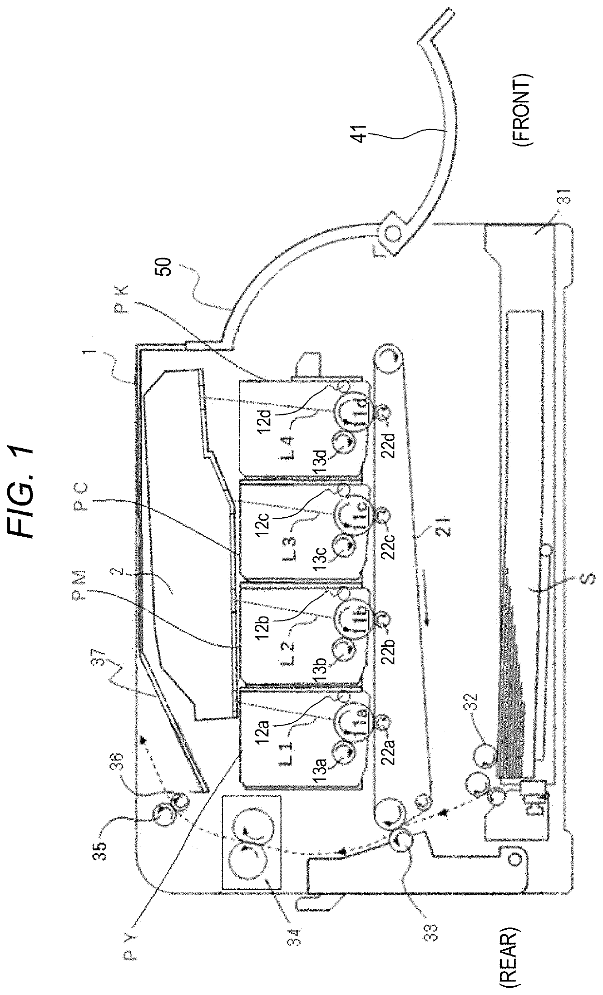
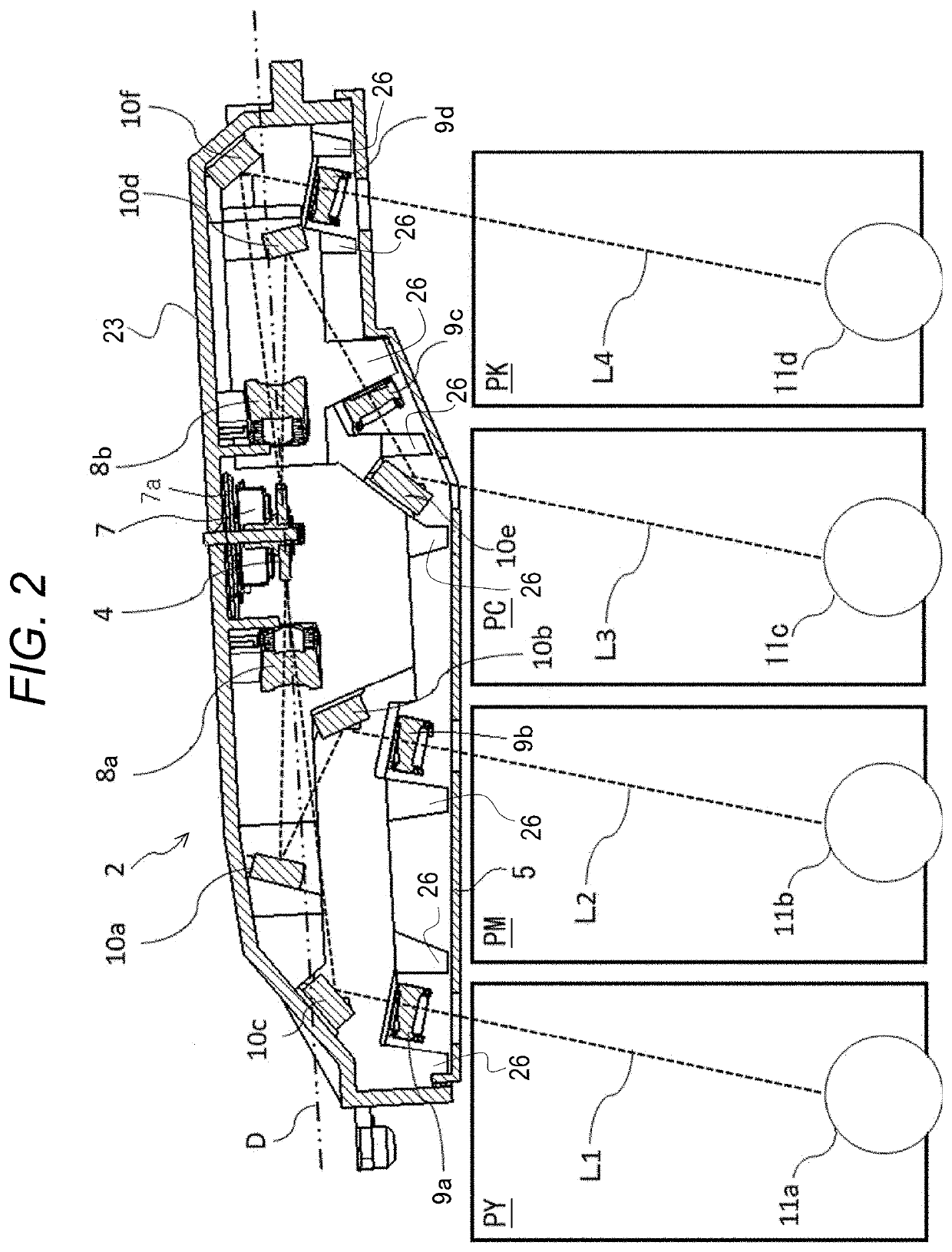
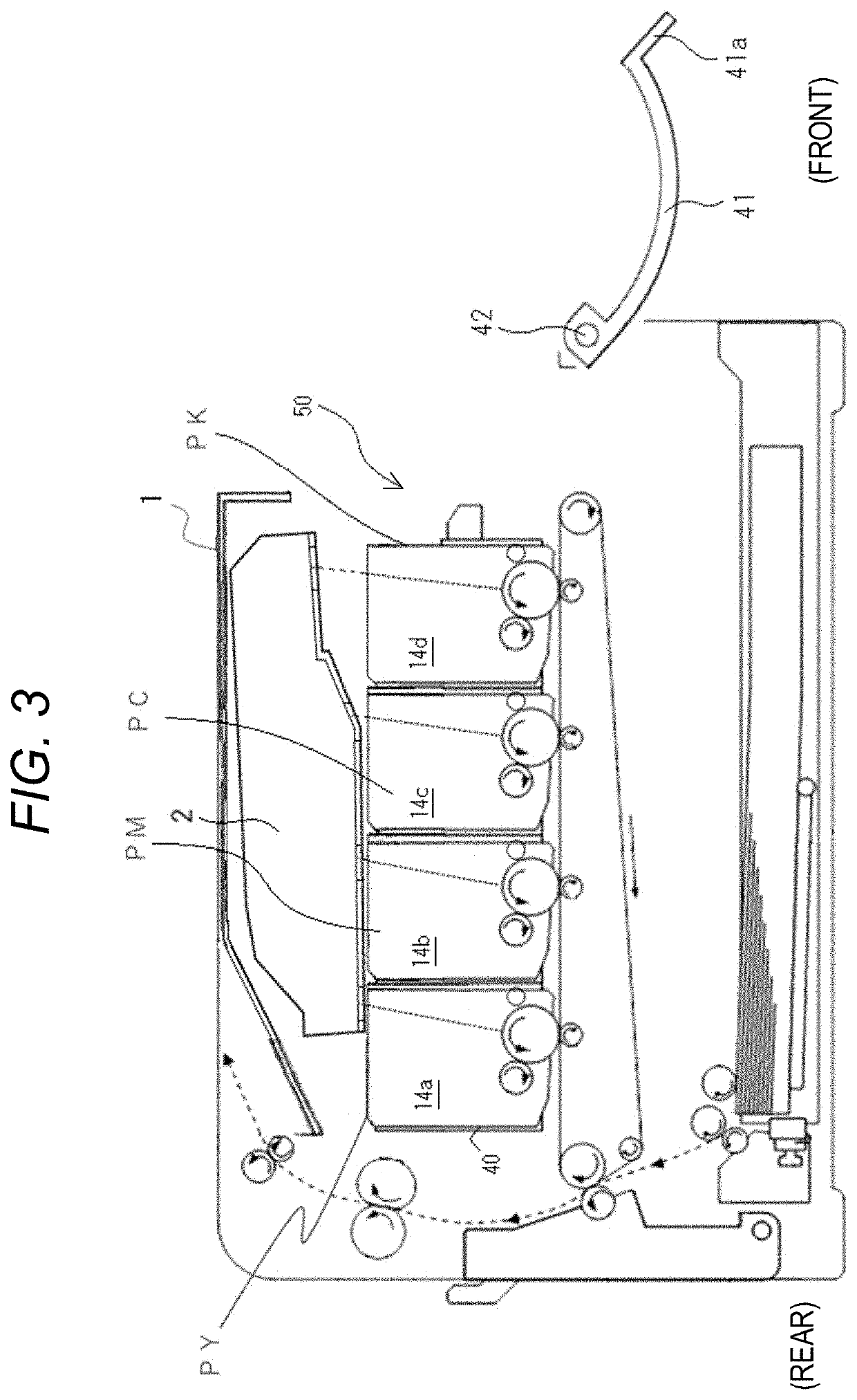
[0038]FIG. 1 is a schematic sectional view for illustrating a configuration of an image forming apparatus 1 of a first embodiment. The image forming apparatus 1 has a configuration in which an optical scanning device 2 and process cartridges PY, PM, PC and PK are mounted on a main body. The image forming apparatus 1 of this embodiment superimposes toner images, which are obtained by forming visible images with toners of four colors including yellow (Y), magenta (M), cyan (C), and black (K) on one another, to thereby form a full color image. As illustrated in FIG. 1, the process cartridges PY, PM, PC, and PK have the same configuration. The letters “a”, “b”, “c”, and “d” on ends of reference symbols of members of the respective process cartridges indicate that the members denoted thereby are members of the process cartridges PY, PM, PC, and PK, respectively. In the following description, the description of “a”, “b”, “c”, and “d” on the ends of the reference s...
second embodiment
[0063]In the first embodiment, the description has been given of the embodiment of the image forming apparatus with the configuration in which the optical scanning device is disposed vertically above the process cartridges. In a second embodiment, a description is given of an embodiment of an image forming apparatus with a configuration in which an optical scanning device is installed vertically below process cartridges and a feed cassette (moving unit) that feeds recording materials is disposed vertically below the optical scanning device.
[Image Forming Apparatus]
[0064]FIG. 9 is a schematic sectional view for illustrating a configuration of an image forming apparatus 100 of the second embodiment. The image forming apparatus 100 has a configuration in which an optical scanning device 101 and image forming units of yellow (y), magenta (m), cyan (c), and black (K) are mounted on a main body. The image forming apparatus 100 of this embodiment superimposes toner images, which are obtain...
third embodiment
[0088]In the first and second embodiments, the description has been given of the backup portions which are rib portions for protecting the optical components and the like arranged in the optical scanning device when the cover member of the optical scanning device is pressed. Herein, the optical components and the like are protected so as to be prevented from coming into contact with the cover member bent by being pressed. In a third embodiment, a description is given of processing and material of the cover member for protecting, from static electricity, electronic devices in the optical scanning device including the backup portions as described above.
[Cover Member of Optical Scanning Device]
[0089]FIG. 15 is a perspective view of an optical scanning device 401 having an outer shape similar to that of the optical scanning device 101 described in the second embodiment. The optical scanning device 401 includes an optical box 403 and a cover member 405, and FIG. 15 is a perspective view ...
PUM
 Abstract
Description
Claims
Application Information
 - R&D
- Intellectual Property
- Life Sciences
- Materials
- Tech Scout
- Unparalleled Data Quality
- Higher Quality Content
- 60% Fewer Hallucinations
Browse by: Latest US Patents, China's latest patents, Technical Efficacy Thesaurus, Application Domain, Technology Topic, Popular Technical Reports.
© 2025 PatSnap. All rights reserved.Legal|Privacy policy|Modern Slavery Act Transparency Statement|Sitemap|About US| Contact US: help@patsnap.com


