
Electronic apparatus

a technology of electronic equipment and auxiliary components, applied in the field of electronic equipment, can solve problems such as inconvenience for users, and achieve the effect of improving user experien

Pending Publication Date: 2022-06-23
CANON KK
View PDF1 Cites 0 Cited by
  • Summary
  • Abstract
  • Description
  • Claims
  • Application Information

AI Technical Summary

Benefits of technology

The present invention is about an electronic device with a finder that can be extended or retracted. The invention prevents the finder from accidentally transitioning to an extended state when it is only meant to be projected.

Problems solved by technology

Therefore, if the position changes from the position when in use to the position when not in use due to an unintended contact with the finder eyepiece during operation, the convenience for the user may be impaired.

Method used


Image

  • Electronic apparatus
  • Electronic apparatus
  • Electronic apparatus

Examples


Embodiment Construction

[0022]A preferred embodiment of the present invention will now be described in detail with reference to the accompanying drawings. In each drawing, the same reference numerals are provided for components that are the same, and redundant descriptions will be omitted. Although an example of an application to an image pickup apparatus provided with a movable finder is described in the present embodiment, the present invention can be applied to various electronic devices provided with a movable display unit.

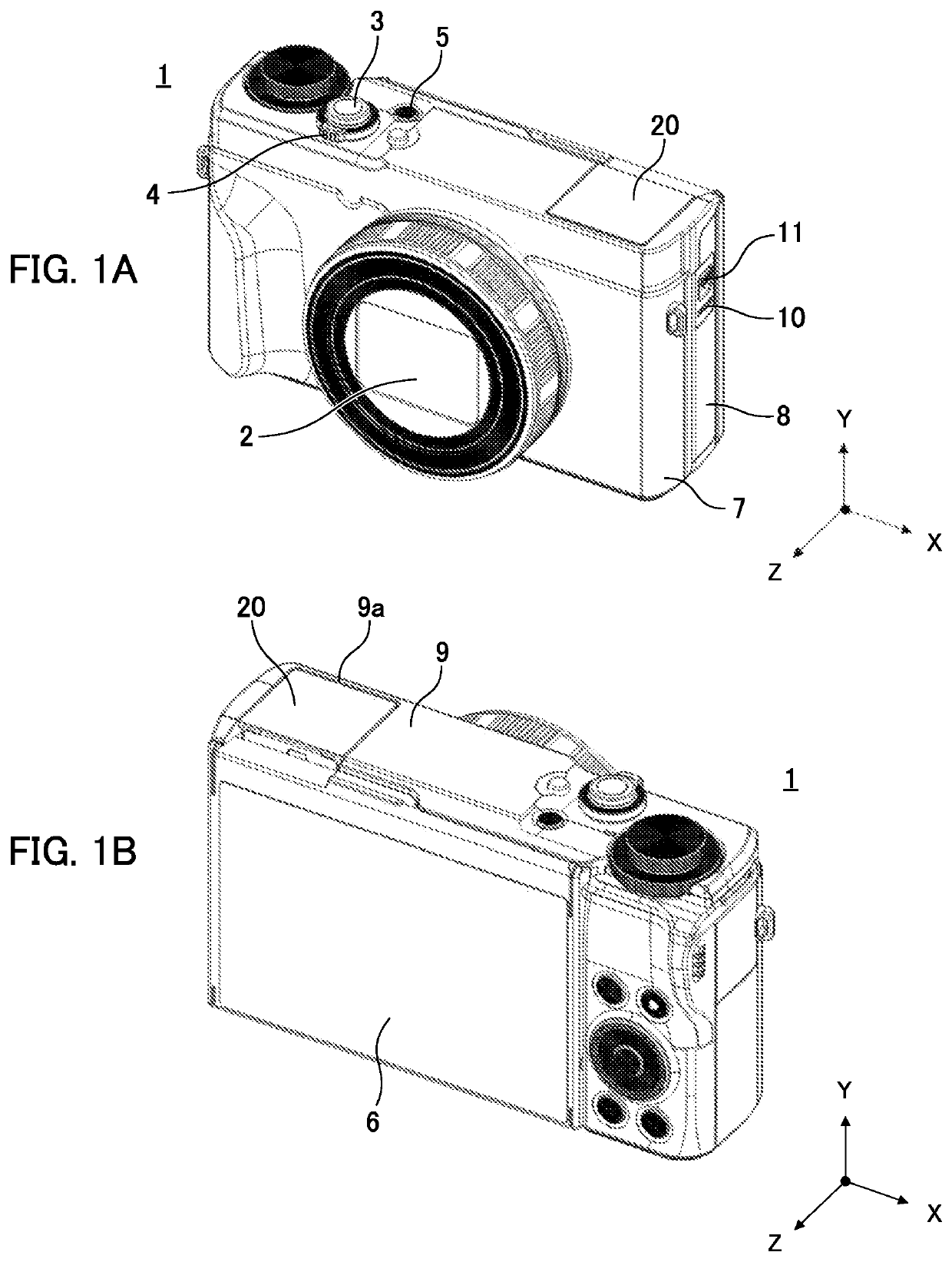
[0023]With reference to FIGS. 1A and 1B, a configuration example of an image pickup apparatus 1 according to the present embodiment will be described. FIGS. 1A and 1B are perspective views of the image pickup apparatus 1 and illustrate a state in which a finder unit 20 is retracted. FIG. 1A is a front perspective view of the image pickup apparatus 1 and FIG. 1B is a rear perspective view of the image pickup apparatus 1. In the image pickup apparatus 1 shown in FIG. 1A, the right and ...


PUM


Abstract

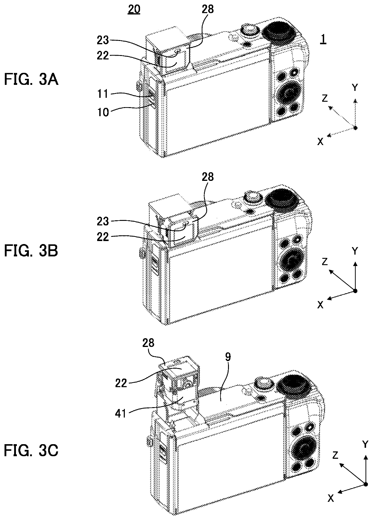
An electronic view finder unit provided in an image pickup apparatus is movable between a retracted state in which the electronic view finder unit is retracted in a main body and a projecting state in which the electronic view finder unit projects from the main body. The electronic viewfinder unit includes a viewfinder having a display device, an eyepiece portion, and a lens holder. The eyepiece portion is slidable between an inserted position and an extracted position in the optical axis direction of the lens. At the position where, in the projecting state, the eyepiece portion is extracted, the viewfinder is rotatable around an axis orthogonal to the optical axis of the lens. Both during the rotating operation of the viewfinder and in a state in which the rotating operation has completed, the movement of the eyepiece portion from the extracted position to the inserted position is limited.

Description

BACKGROUND OF THE INVENTIONField of the Invention[0001]The present invention relates to an electronic apparatus provided with a movable display.Description of the Related Art[0002]Some electronic viewfinders (hereinafter, referred to simply as a “finder”) provided in an image pickup apparatus have a configuration in which the finder can move between a state in which the finder is retracted in a main body (retracted state) and a state in which the finder projects from the main body (projecting state). In image pickup apparatus disclosed in Japanese Patent Laid-Open Publication No. 2015-227901, when not in use, the finder is retracted in the camera body, and when in use, the finder slides toward the upper portion of the camera body due to a lever operation and the finder transitions to a projecting state.[0003]In the prior art disclosed in Japanese Patent Application Laid-Open No. 2015-227901, it is impossible to change an angle of the finder in accordance with a shooting posture of a...

Claims


Application Information

Patent Timeline
Patent Type & Authority Applications(United States)
IPC IPC(8): H04N5/225H04N5/232G02B13/06G02B17/04
CPCH04N5/225251G02B17/04G02B13/06H04N5/232939G03B13/06G02B25/001G02B23/14H04N23/531H04N23/60H04N23/65H04N23/63H04N23/633
Inventor KEI, HIDETOSHI
Owner CANON KK
Learn More