Oil pressure control device

a technology of oil pressure control and control device, which is applied in the direction of water supply installation, machine/engine, drawing-off water installation, etc., can solve the problems of destabilization of line pressure, deformation of line pressure, and inability of valves and the like to operate normally, so as to achieve accurate oil pressure control

Inactive Publication Date: 2013-03-12
TOYOTA JIDOSHA KK
View PDF16 Cites 0 Cited by
  • Summary
  • Abstract
  • Description
  • Claims
  • Application Information

AI Technical Summary

Benefits of technology

[0014]Owing to this configuration, in the foreign matter discharge period, the timings for varying the current values of the first solenoid valve and the second solenoid valve are different from each other. Therefore, when the output pressure of the second control valve at the time of pressure regulation which is based on the pilot pressure from the second solenoid valve increases, the original pressure of the second control valve as the output pressure of the first control valve which is based on the pilot pressure from the first solenoid valve decreases, whereas when the output pressure of the second control valve at the time of pressure regulation which is based on the pilot pressure from the second solenoid valve decreases, the original pressure of the second control valve as the output pressure of the first control valve which is based on the pilot pressure from the first solenoid valve increases. Accordingly, even when the first solenoid valve and the second solenoid valve are simultaneously subjected to the foreign matter discharge treatment, the occurrence of a situation in which an actuator or the like as a controlled object is adversely influenced due to a high output pressure of the second control valve is avoided. As a result, the foreign matter discharge treatment can be carried out simultaneously for the two solenoid valves without greatly influencing the controlled oil pressure of the oil pressure control device, and a swift transition to subsequent oil pressure control can be made.
[0016]Owing to this configuration, the supplied current is temporarily set to the intermediate current value in starting to make a change from the maximum current value to the minimum current value. Thus, the value of the supplied current upon completion of the change to the minimum current value is restrained from undershooting, and a more swift transition to subsequent oil pressure control can be made.
[0018]Owing to this configuration, the foreign matter discharge treatment can be carried out simultaneously for the two solenoid valves without greatly influencing the controlled oil pressure of the oil pressure control device. As a result, the spools of the linear solenoid valves are prevented from having the foreign matters stuck therein, and from deteriorating in sliding performance or seizing due to sludge produced around lands of the spools.
[0020]Owing to this configuration, the foreign matter discharge treatment can be carried out quickly without adversely influencing the actuator constituting part of the vehicular continuously variable transmission.
[0022]According to the invention, the oil pressure control device capable of carrying out the foreign matter discharge treatment simultaneously for the plurality of the solenoid valves without greatly influencing the controlled oil pressure of oil pressure control and carrying out the foreign matter discharge treatment quickly in the oil pressure control circuit that is equipped with the plurality of the solenoid valves and the means for carrying out the foreign matter discharge treatment for the solenoid valves so as to perform the oil pressure control accurately can be provided.

Problems solved by technology

When foreign matters mingle in an oil pressure control circuit, the valves and the like cannot operate normally.
In the case where stable control is constantly required during the driving of an automobile as in the case of line pressure control or the like, when an output port simultaneously communicates with a supply port and a drain port at the time of pressure regulation, a deficiency in the capacity of an oil pump or destabilization of line pressure is caused.
Nonetheless, in the case of a circuitry in which a first control valve is controlled with a pilot pressure from a first solenoid valve and a second control valve is controlled with a pilot pressure from a second solenoid valve, when a foreign matter discharge treatment for the first solenoid valve is carried out during a foreign matter discharge treatment for the second solenoid valve, a considerable load is applied to an object controlled by the second control valve.
As a result, there is a problem in that the foreign matter discharge treatment is time-consuming.
Therefore, in the case where foreign matter discharge control is performed prior to, for example, neutral control of a vehicle mounted with a continuously variable transmission, a sufficient time cannot be ensured for neutral control.
In consequence, there is a problem in that an effect of improving fuel consumption through neutral control is lost as well.

Method used


Image

  • Oil pressure control device
  • Oil pressure control device
  • Oil pressure control device

Examples


first embodiment

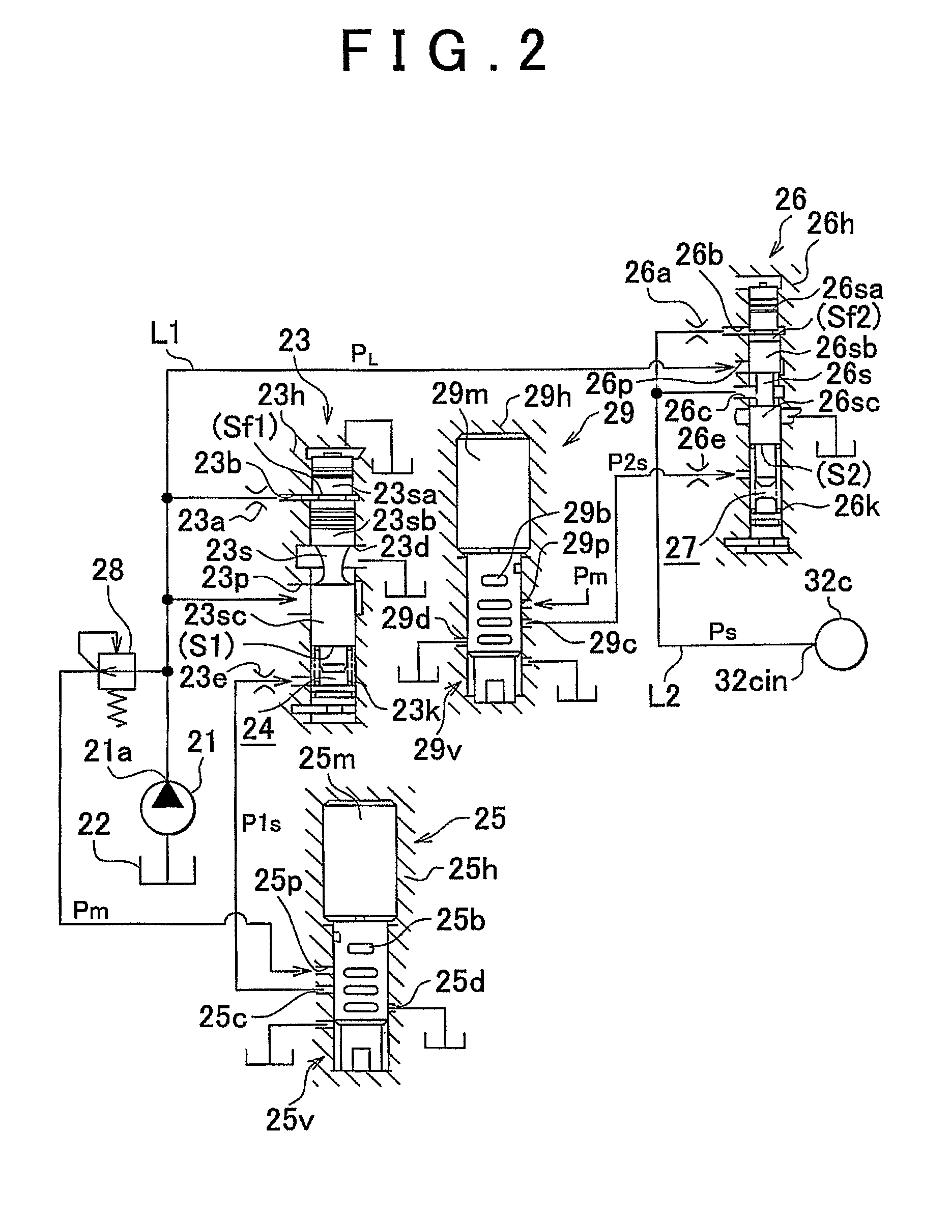
[0032]FIGS. 1 to 6 are views showing the first embodiment of an oil pressure control device according to the invention. These figures show an example in which the invention is applied to an oil pressure control device for controlling the pressure of a working fluid in a belt-type continuously variable transmission for an automobile.

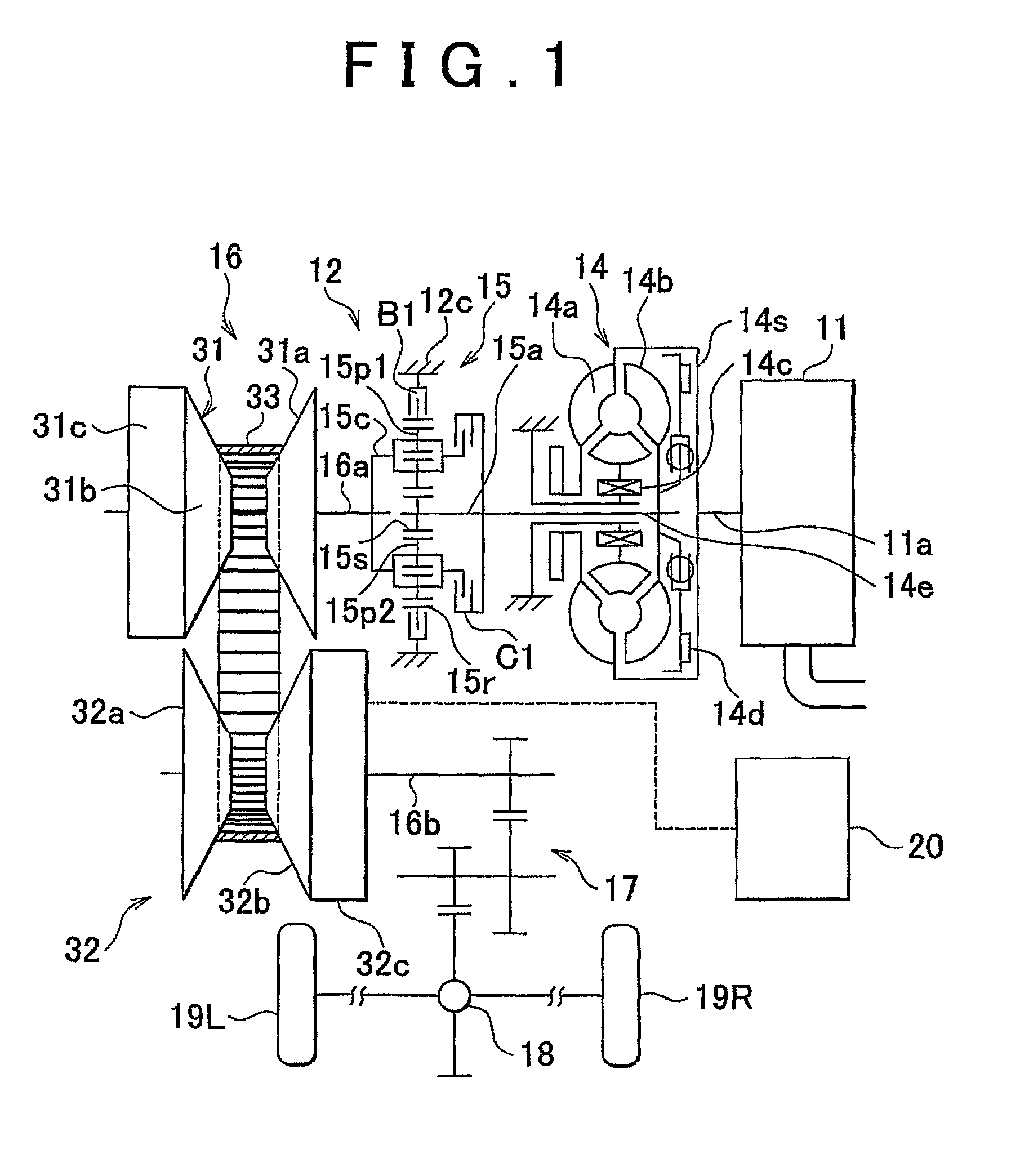
[0033]First of all, the configuration of the oil pressure control device will be described. As shown in FIG. 1 as a skeleton diagram of a power transmission path of the automobile, a vehicle (the automobile not entirely shown) according to this embodiment of the invention is mounted with an engine 11 as a prime mover, and a transmission 12 capable of changing the speed of the rotational output of this engine 11. The transmission 12 includes a torque converter 14, a forward / backward changeover gear mechanism 15, a belt-type continuously variable shift mechanism 16, and an oil pressure control portion 20. A power transmission path is set such that an output...

second embodiment

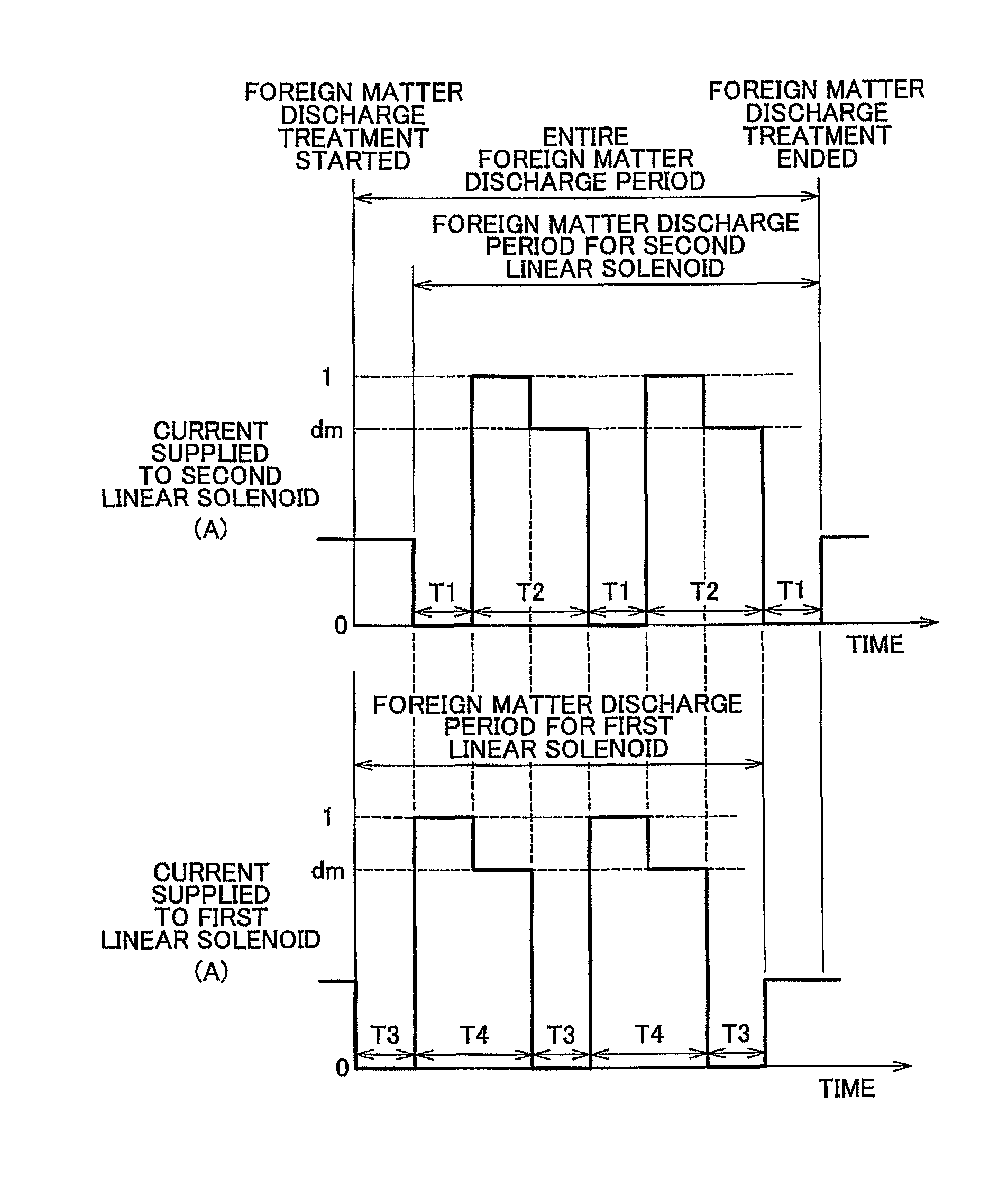
[0081]FIG. 7 is a view showing another embodiment of an oil pressure control device according to the invention. This embodiment of the invention is different from the first embodiment of the invention in means for performing foreign matter discharge control upon fulfillment of the foreign matter discharge condition and the contents of the foreign matter discharge treatment, but identical to the foregoing embodiment of the invention in other configurational details and the foreign matter discharge condition itself. In this case, therefore, the following description will focus especially on what is different from the foregoing embodiment of the invention, using the symbols shown in FIGS. 1 to 6 for the same component elements as in the foregoing embodiment of the invention.

[0082]As shown in FIG. 7, in this embodiment of the invention, the current values of the currents supplied to the two linear solenoid valves 25 and 29 in the period of the simultaneous foreign matter discharge treat...


PUM


Abstract

An oil pressure control device includes a plurality of solenoid valves, and a foreign matter discharge unit which carries out foreign matter discharge treatment for a treatment period composed of a first period T1 in which a current smaller than a predetermined value is supplied to one of the solenoid valves and a second period T2 in which a current equal to or larger than the predetermined value is supplied to the one of the solenoid valves, and makes timings for varying the current values different from one another so as to start supplying a current equal to or larger than the predetermined current value to another one of the solenoid valves at the beginning of the first period T1, and to start supplying a current smaller than the predetermined value to the another one of the solenoid valves at the beginning of the second period T2.

Description

BACKGROUND OF THE INVENTION[0001]1. Field of the Invention[0002]The invention relates to an oil pressure control device that carries out a treatment of discharging foreign matters that have mingled in a circuit, and more particularly, to an oil pressure control device for carrying out a foreign matter discharge treatment for a plurality of solenoid valves.[0003]2. Description of the Related Art[0004]In each of various oil pressure control circuits, a solenoid valve such as an electromagnetic proportional control valve or the like, which operates a valve body with the aid of a solenoid in order to control the pressure of a working fluid for actuating a group of actuators, is employed. The pressure and flow rate of the working fluid that are required for actuation of the actuators are ensured by, for example, operating another control valve using an output pressure of the solenoid valve as a pilot pressure. When foreign matters mingle in an oil pressure control circuit, the valves and...

Claims


Application Information

Patent Timeline
Patent Type & Authority Patents(United States)
IPC IPC(8): F16K31/06F16H59/68F16H61/12F16H61/66F16H61/662
CPCF16H61/12F16H61/66259F16H2061/1264Y10T137/0324Y10T137/0402Y10T137/4245Y10T137/7722Y10T137/86622
Inventor OGATA, YUSUKESOGA, YOSHINOBU
Owner TOYOTA JIDOSHA KK
Why Eureka
Try Eureka