
Apparatus and method for manufacturing absorbent core used in disposable wearable article

a technology of absorbent core and absorbent material, which is applied in the field of apparatus and a manufacturing method of absorbent core used in disposable wearable articles, can solve the problem that two layers are likely to be out of alignment during transporting or using absorbent articles

Pending Publication Date: 2022-07-07
ZUIKO CORP
View PDF0 Cites 0 Cited by
  • Summary
  • Abstract
  • Description
  • Claims
  • Application Information

AI Technical Summary

Benefits of technology

The present invention provides a method and apparatus for making an absorbent core with different thickness parts that don't align with each other.

Problems solved by technology

Since the convention technique overlaps the two layers by simply putting the one on the other, the two layers are likely to be out of alignment during transporting or using the absorbent article.

Method used


Image

  • Apparatus and method for manufacturing absorbent core used in disposable wearable article
  • Apparatus and method for manufacturing absorbent core used in disposable wearable article

Examples


embodiment 1

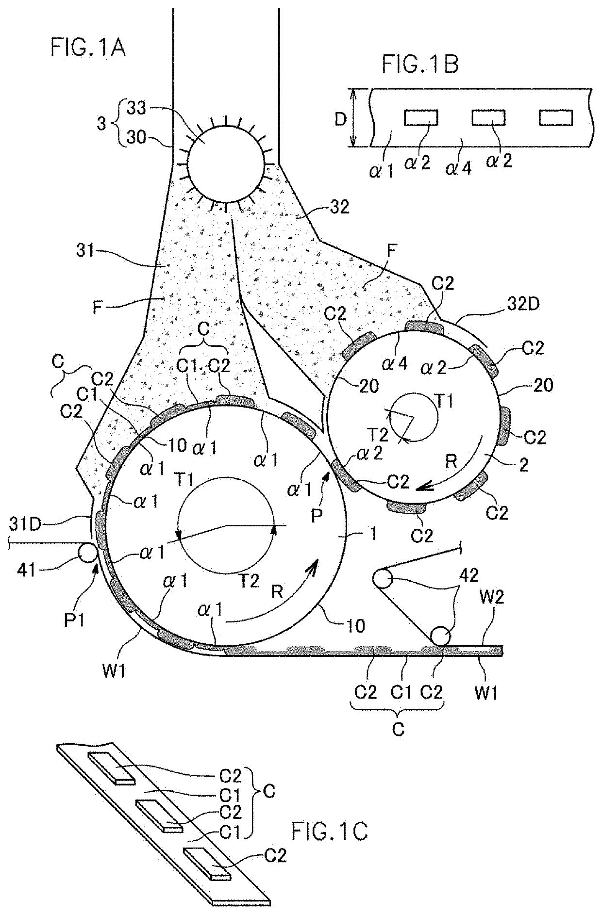
[0051]FIG. 1 shows an

[0052]As shown in FIG. 1, a manufacturing device includes a feed device 3, a first drum 1, and a second drum 2.

[0053]The feed device 3 includes a cylindrical case 30 and a defibrating machine 33. The defibrating machine 33 defibrates (comminutes) pulp fed from the upstream to produce fluff pulp (fiber). The fluff pulp filled in the case 30 passes through a first duct portion 31 and a second duct portion 32, and is stacked on an outer circumferential portion 10 of the first drum 1 and an outer circumferential portion 20 of the second drum 2 due to negative pressure from respective suction chambers (not shown) of the first and second drums 1, 2. The defibration and stacking described above are well-known technique in the art, and they are disclosed in JP2009-112438 A, for example.

[0054]Note that high molecular compound particles (super absorbent polymer particles), as it is called SAP, having high absorbing capacity may be added as a construction material for the ...

embodiment 2

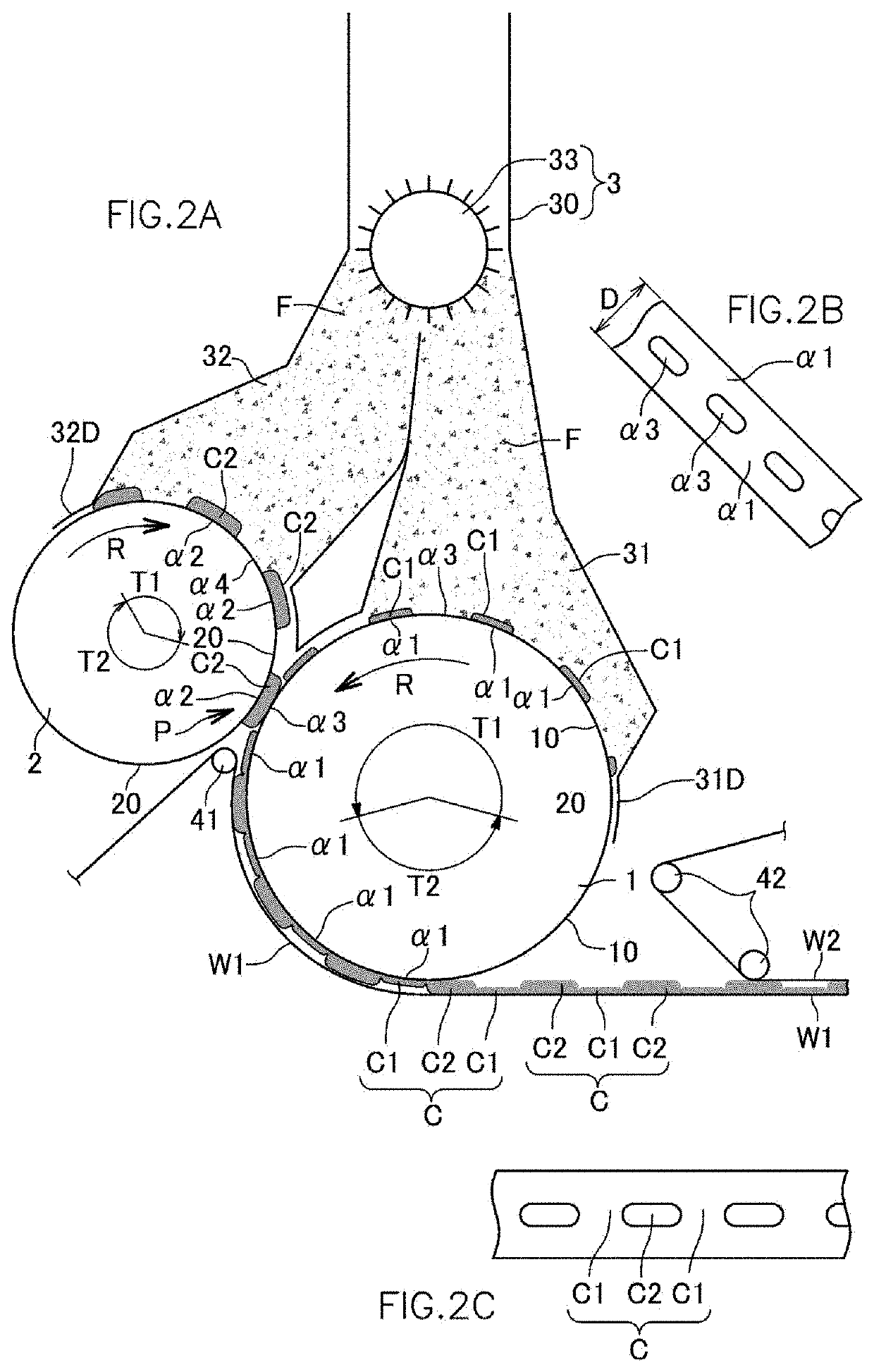
[0080]FIG. 2 shows an

[0081]The embodiment 2 will be mainly described for different part from the embodiment 1.

[0082]In the present embodiment, an inhibition area α3 is provided in the first drum 1 in addition to the first area α1. In the inhibition area α3, the stacking of the fiber F is inhibited (prevented). For weakening negative pressure suction, the mesh porosity in the outer circumferential portion 10 in the inhibition area α3 may be set to be small. The first drum 1 and the second drum 2 contact with each other at the hand-over point P as follows.

[0083]The both drums contact at the point P so that the thick portion C2 stacked on the second drum 2 is passed (handed over) from the second drum 2 to the inhibition area α3 of the first drum 1. The hand-over is performed in a state where the fiber F is clung to and stacked on the first area α1, except the inhibition area α3, of the first drum 1 while the fiber F is not stacked on the inhibition area α3, where stacking of the fiber ...


PUM


Abstract

A method for manufacturing an absorbent core uses a feed device feeding crushed fiber, a first drum provided with a first area, where the crushed fiber is sucked and stacked, and a second drum provided with a second area, where the crushed fiber is sucked stacked, the second area being smaller than the first area, the method includes a step of forming a thick portion on the second area of the second drum by stacking the fiber fed from the feed device; a step of transferring the thick portion to a predetermined position in the first area; and a step of forming a thin portion on the first area of the first drum by stacking the fiber fed from the feed device around the transferred thick portion with the transferred thick portion placed on the first area.

Description

TECHNICAL FIELD[0001]The present invention relates to an apparatus and a method for manufacturing an absorbent core used in a disposable wearable article.BACKGROUND ART[0002]For manufacturing an absorbent article such as diaper, there has been a technique in which a partial area in an absorbent core is made have different thickness from the other area in the core. In the technique, one of the two fiber stacking drums forms a first absorbent layer; another of the two fiber stacking drums forms a second absorbent layer, which has a smaller area than the first absorbent layer; and the first and second absorbent layers overlap with each other, thereby producing an absorbent core, which has a partial area thicker than the rest.CITATION LISTPatent Literature[0003][First patent document] JP 2,541,558 B2 (FIG. 1)SUMMARY OF INVENTION[0004]Since the convention technique overlaps the two layers by simply putting the one on the other, the two layers are likely to be out of alignment during tran...

Claims


Application Information

Patent Timeline
IPC IPC(8): A61F13/15D04H1/736
CPCA61F13/15658D04H1/736A61F2013/15926D10B2509/026D10B2501/00A61F13/15764A61F13/15642
Inventor UMEBAYASHI, TOYOSHI
Owner ZUIKO CORP
Learn More