Method and Apparatus for Making a Braided Stent with Spherically Ended Wires

a spherical end and wire technology, applied in the direction of laser beam welding apparatus, manufacturing tools, other manufacturing equipment/tools, etc., can solve the problems of high temperature gradient, high manufacturing error probability, and increase the distance from the laser center, so as to reduce the tendency of wires to fall off, reduce the likelihood of manufacturing errors, and secure the relationship

Inactive Publication Date: 2006-08-24
AMS RES CORP
View PDF15 Cites 3 Cited by
  • Summary
  • Abstract
  • Description
  • Claims
  • Application Information

AI Technical Summary

Benefits of technology

[0039] It is envisioned that the present invention includes pins or protuberances that are sized to snugly fit within the diamond shaped holes defined by the strands of the braided stent stock. Sizing the pins thusly results in a more secure relationship between the stent stock and the mandrel and reduces the likelihood of manufacturing errors due to stock movement.
[0040] The combination of the progressive engagement pattern described above with pins sized to snugly fit within the diamond shaped holes defined by the strands of the braided stent stock ensures that the mandrel adequately compensates for irregularities in the braided stent design.
[0041] In another aspect, the present invention provides a device for securing a length of stent stock, as described above, at a predetermined axial position along the device, which includes two sets of spaced apart pins separated by a cutting groove. Providing two sets of pins, preferably including four pins per set, and a cutting groove between the sets, significantly decreases the tendency for the wires to “jump” away from the cutting tool after the cut has been made.
[0042] In other aspects of the present invention, the mandrel includes three sets of pins, preferably having at least two pins per set, more preferably three pins per set, and even more preferably four pins per set, and two cutting grooves juxtaposed between each of the sets of pins such that one set of pins lies between the cutting grooves while the remaining sets are found on the outside of each groove. This arrangement is advantageous in that it facilitates a faster manufacturing process, and provides more accurate positioning of wires and intersections relative to the position of the heat source, than does the use of fewer pins.
[0043] More specifically, the braided stent stock is placed on the mandrel so that numerous stents may be cut therefrom. Though each cut results in two ends of stock, usually only one end has spheres formed on the ends of the individual strands. Another cut must be made to form spheres on the other end of the stock. In other words, in order to cut a plurality of stents with spherically ended strands from a single length of stock, a certain amount of waste must be allocated between each strand. Providing two grooves, spaced apart by a distance which will result in the length of the scrap piece, allows the end of one stent to be cut, and the beginning of another stent to be cut, without adjusting the position of the stent stock on the mandrel. This is also advantageous in that it results in a predictable, repeatable length of scrap between each stent. In this embodiment, three sets of pins are provided so the strands of the stent stock are secure on either side of each cutting groove. This prevents each strand from “jumping” out of alignment after it is cut.
[0044] In one aspect of the present invention, springs are provided, operably attached to each pin, thereby biasing the pins toward an inward position whereby a smooth outer mandrel surface is provided when the activation dowel is not inserted. This arrangement facilitates sliding a newly formed stent and scrap pieces off of the mandrel and also allows the remaining length of stent stock to be slid along the length of the mandrel so that another stent may be cut therefrom.

Problems solved by technology

In other words, the temperature gradient, as the distance from the center of the laser increases, is very steep.

Method used


Image

  • Method and Apparatus for Making a Braided Stent with Spherically Ended Wires
  • Method and Apparatus for Making a Braided Stent with Spherically Ended Wires
  • Method and Apparatus for Making a Braided Stent with Spherically Ended Wires

Examples


Embodiment Construction

[0068] Device

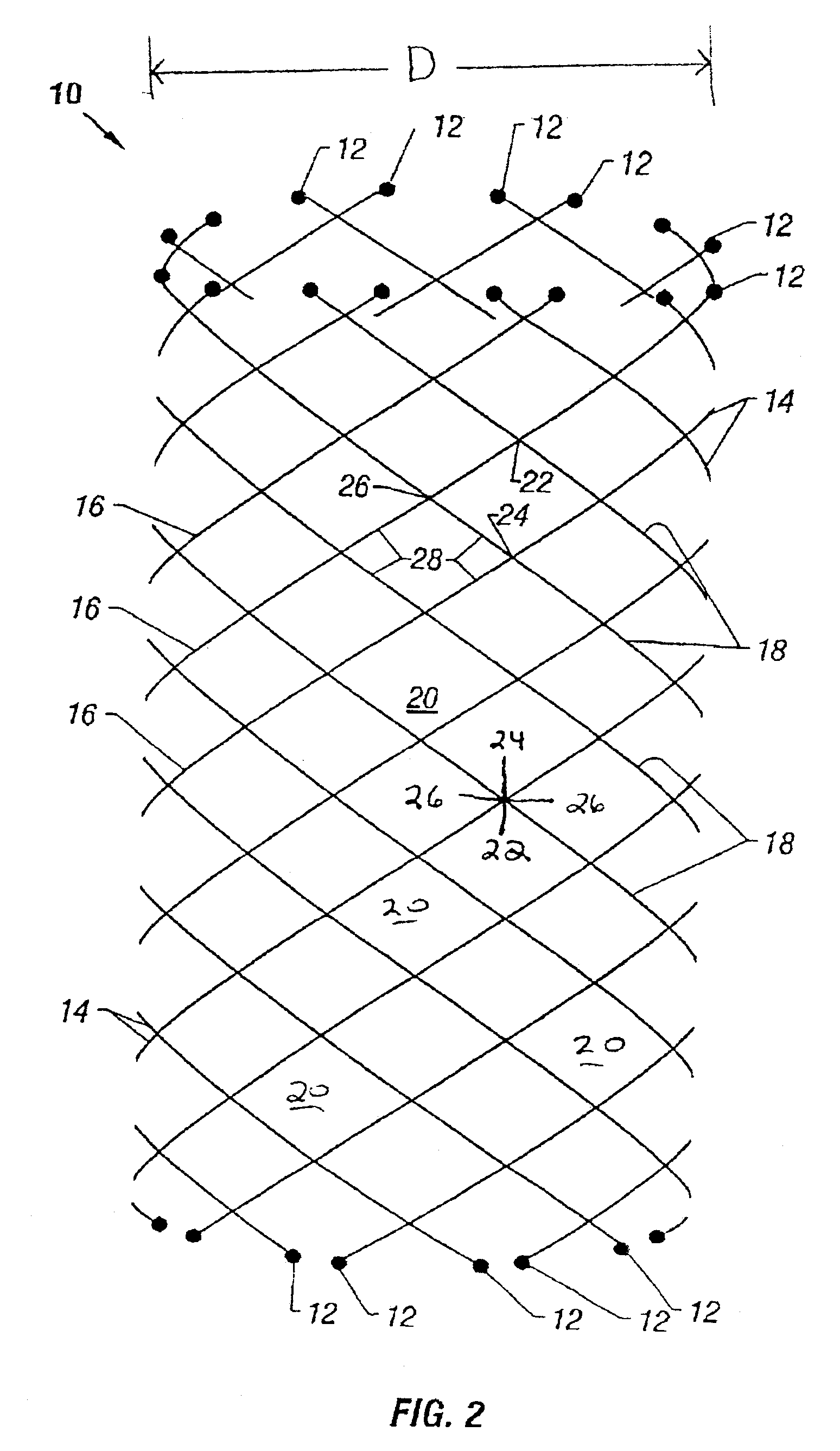
[0069] Referring now to the figures, and first to FIG. 2, there is shown a braided stent 10 to which the various embodiments of the devices and methods of the present invention are directed to forming. Stent 10 is formed such that the cut ends 12 of the wires or strands 14 are substantially spherically shaped.

[0070] Stent 10 is a segment cut from braided stent stock, which is made up of a plurality of strands 14. Strands 14 are braided such that half of the strands 14 form left-handed helixes 16 and the other half of the strands 14 form right-handed helixes 18. The various helixes 16 and 18 are alternately woven together to define a plurality of diamond-shaped openings 20. Openings 20 have upper apexes 22, lower apexes 24 and side apexes 26, which are formed by the intersections of the individual strands 14. The strand lengths between the intersections define the sides 28 of the diamonds 20. It is readily apparent from the figure that any given intersection of two str...


PUM

PropertyMeasurementUnit
inner diameteraaaaaaaaaa

Abstract

A method and apparatus for cutting a braided wire stent to a predetermined length such that a ball or sphere is formed on the end of each cut wire of the stent. These spheres are advantageous in that they provide added comfort to the patient and also act against the other wires of the stent to prevent the stent from becoming unbraided during the process of collapsing and expanding the stent such as is done when the stent is being inserted into a patient. The apparatus releasably holds and precisely positions the wires while the spheres are being formed.

Description

CLAIM FOR PRIORITY [0001] This divisional patent application claims priority to United States utility patent application Ser. No. 09 / 749,291, filed Dec. 27, 2000, and entitled “Method and Apparatus for Making a Braided Stent with Spherically Ended Wires.” The identified utility patent application is herein incorporated by reference.TECHNICAL FIELD [0002] The present invention pertains generally to cutting braided stents from stock. BACKGROUND OF THE INVENTION [0003] Stents are generally metal or plastic tubes inserted into a vessel such as the urethra to keep a lumen open. A vast variety of stent materials and designs are available. A few examples of available designs include braided tubes, wire springs, and tubes having a plurality of holes formed therein to provide flexibility. It is preferable that a stent design provides a tube which can be stretched or otherwise manipulated to reduce the diameter of the tube while the stent is being inserted, and which expands to resume an orig...

Claims


Application Information

Patent Timeline
Patent Type & Authority Applications(United States)
IPC IPC(8): B23P23/04A61F2/90B23K26/38
CPCA61F2/90Y10T29/5102B23K26/38
Inventor NACHREINER, GARYRYKHUS, ROBERT L. JR.HAUSCHILD, SIDNEYPOLYAK, MARK
Owner AMS RES CORP
Why Eureka
Try Eureka