Measuring system

Pending Publication Date: 2022-07-14
M&H INPROCESS MESSTECHNIK GMBH
View PDF0 Cites 0 Cited by
  • Summary
  • Abstract
  • Description
  • Claims
  • Application Information

AI Technical Summary

Problems solved by technology

In this known measuring system, it is comparatively complicated to bring the generated measurement

Method used


Image

  • Measuring system
  • Measuring system
  • Measuring system

Examples


Example

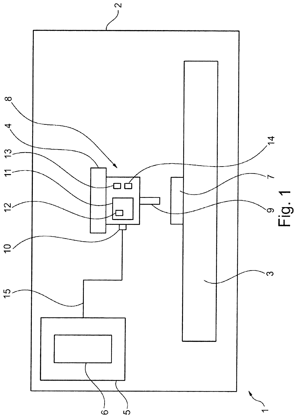
[0053]FIG. 1 shows a schematically illustrated machine 1 with a housing 2, a machine table 3, a movement bar 4 and a control unit 5. By way of example, the machine 1 comprises a storage module 6 which is present at the control unit 5, for example. A measurement object 7 is arranged on the machine table 3 in exemplary fashion.

[0054]Advantageously, a measuring system 8 is present in a manner arranged on the machine 1. The measuring system 8 comprises a measuring instrument 9, an interface 10 and a controller unit 11. By way of example, the controller unit 11 has a control module 12. Moreover, the measuring system 8 may comprise a storage unit 13 and a timer 14.

[0055]In the embodiment variant according to FIG. 1, the further components of the measuring system 8, such as, for example, the controller unit 11, form a separate compact unit in addition to the measuring instrument 9. According to FIG. 1, the further components of the measuring system 8 are in the form of a compact unit, for ...


PUM


Abstract

A measuring system for detecting measured values by scanning, including a measuring instrument. The measuring system can be arranged on a movement axis of a machine tool or a measuring machine. An object is measured by the measuring instrument generating a measured value during the measurement of the object. The measuring system includes a control unit to process and store the measured value, and a memory unit to store the detected measured value. The measuring system correlates a first measured value with a first position coordinate of the measuring instrument and, starting from the correlation of the first measured value with the first position coordinate, assigns position coordinates uniquely to further measured values detected by the measuring instrument since a movement speed and a movement direction of the measuring instrument during or at the time of the detection of the measured values are known to the measuring system.

Description

CROSS REFERENCE TO RELATED APPLICATIONS[0001]This application is a continuation of International Application No. PCT / EP2020 / 071665 filed Jul. 31, 2020, which designated the United States, and claims the benefit under 35 USC § 119(a)-(d) of German Application No. 10 2019 122 650.3 filed Aug. 22, 2019, the entireties of which are incorporated herein by reference.FIELD OF THE INVENTION[0002]The present invention relates to a measuring system.BACKGROUND OF THE INVENTION[0003]Measuring systems for scanning acquisition of measurement values are known.[0004]A known measuring system comprises an optical measuring instrument which is in a form that is arrangeable on a machine bar of a tool or a measuring machine. A plurality of measurement values, for example, are able to be successively acquired in a time series by means of the optical measuring instrument. Should the measuring instrument be moved over an object to be measured during a measurement, different locations on the object to be me...

Claims


Application Information

Patent Timeline
IPC IPC(8): G01B11/00G01B5/008
CPCG01B11/005G01B5/008G01B21/042B23Q17/24
Inventor WIEST, CHRISTOPH
Owner M&H INPROCESS MESSTECHNIK GMBH
Why Eureka
Try Eureka