Motor coil cooling structure

a cooling structure and motor coil technology, applied in the direction of cooling/ventilation arrangement, magnetic circuit rotating parts, shape/form/construction, etc., can solve the problems of difficult discharge of air, less cooling liquid passing through and out, and inability to achieve uniform temperature distribution in the stator cor

Pending Publication Date: 2022-07-14
TOYOTA JIDOSHA KK
View PDF0 Cites 2 Cited by
  • Summary
  • Abstract
  • Description
  • Claims
  • Application Information

AI Technical Summary

Problems solved by technology

However, the coolant less readily passes through and out of the first flow paths in the stator core under its own weight at an upper portion of the motor.
However, it would be difficult to discharge this air with only the amount of coolant supplied as a result of the centrifugal force of the rotating rotor when the vehicle is restarted.
As it is difficult for the coolant to pass through and out of the first flow paths in the stator core at the upper portion of the motor, when, for example, the motor is subjected to a large travel load when the vehicle is restarted, the upper portion of the stator core is liable to undergo localized heating where the coolant cannot pass through and out readily, with the result that it may not be possible to achieve a uniform temperature distribution in the stator core.
However, the greater the number of radially penetrating first flow paths that are provided, the smaller the amount of coolant available for each of the first flow paths, such that it becomes difficult to secure the aforementioned expulsion pressure.

Method used


Image

  • Motor coil cooling structure
  • Motor coil cooling structure
  • Motor coil cooling structure

Examples


Embodiment Construction

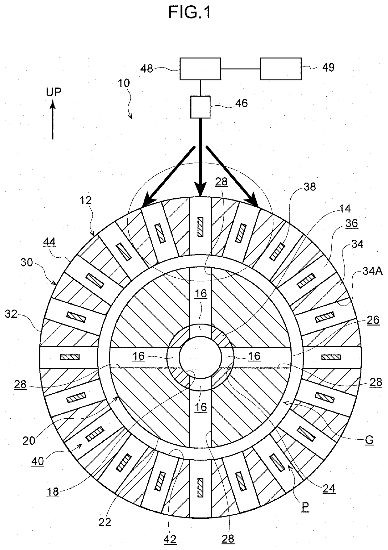
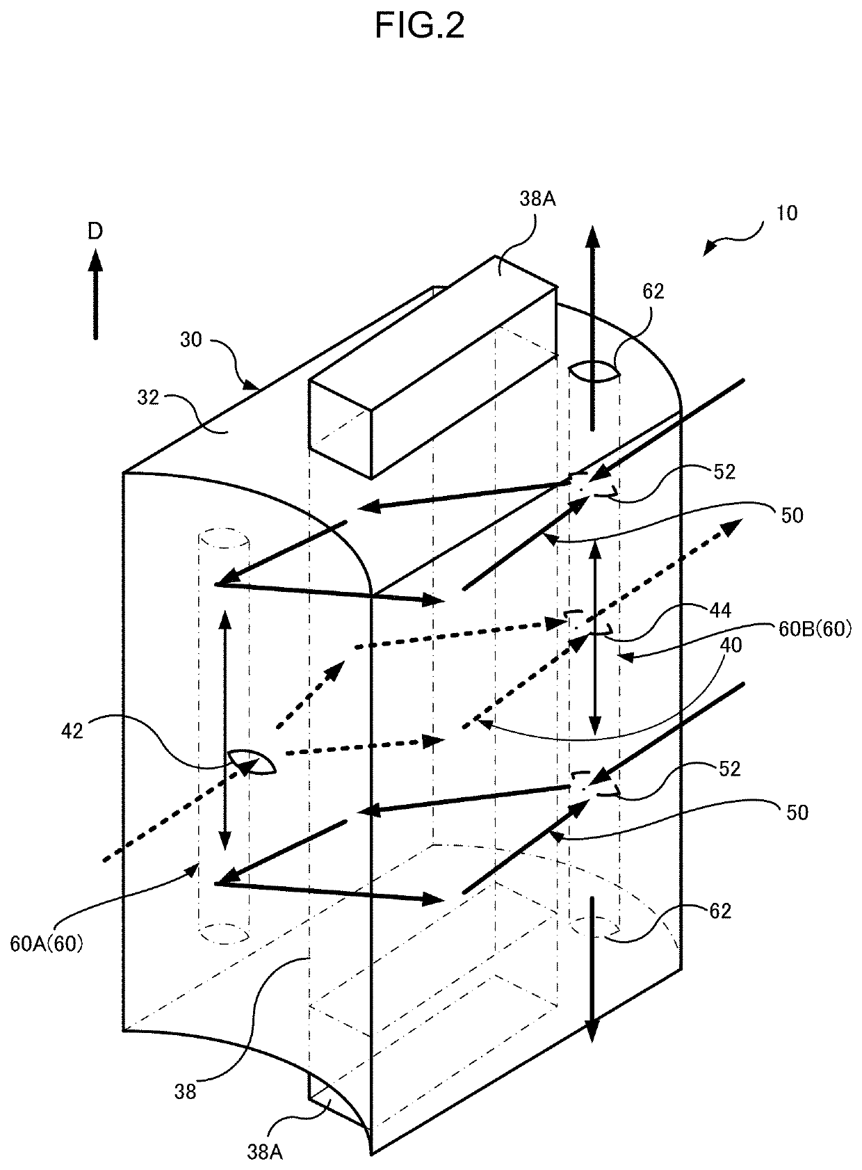
[0030]Detailed explanation follows regarding a first exemplary embodiment according to the present disclosure, with reference to FIG. 1 to FIG. 5. Note that to aid explanation, in FIG. 1, the arrow UP indicates an upward direction with respect to a motor 12, and a direction perpendicular to the page surface corresponds to an axial direction of a rotation shaft 14 of the motor 12. Namely, the motor 12 according to the present exemplary embodiment is mounted transversely in a vehicle (i.e., disposed such that the axial direction of the rotation shaft 14 runs along a horizontal direction). Moreover, to aid explanation, the arrow D in FIG. 2 indicates the axial direction of the rotation shaft.

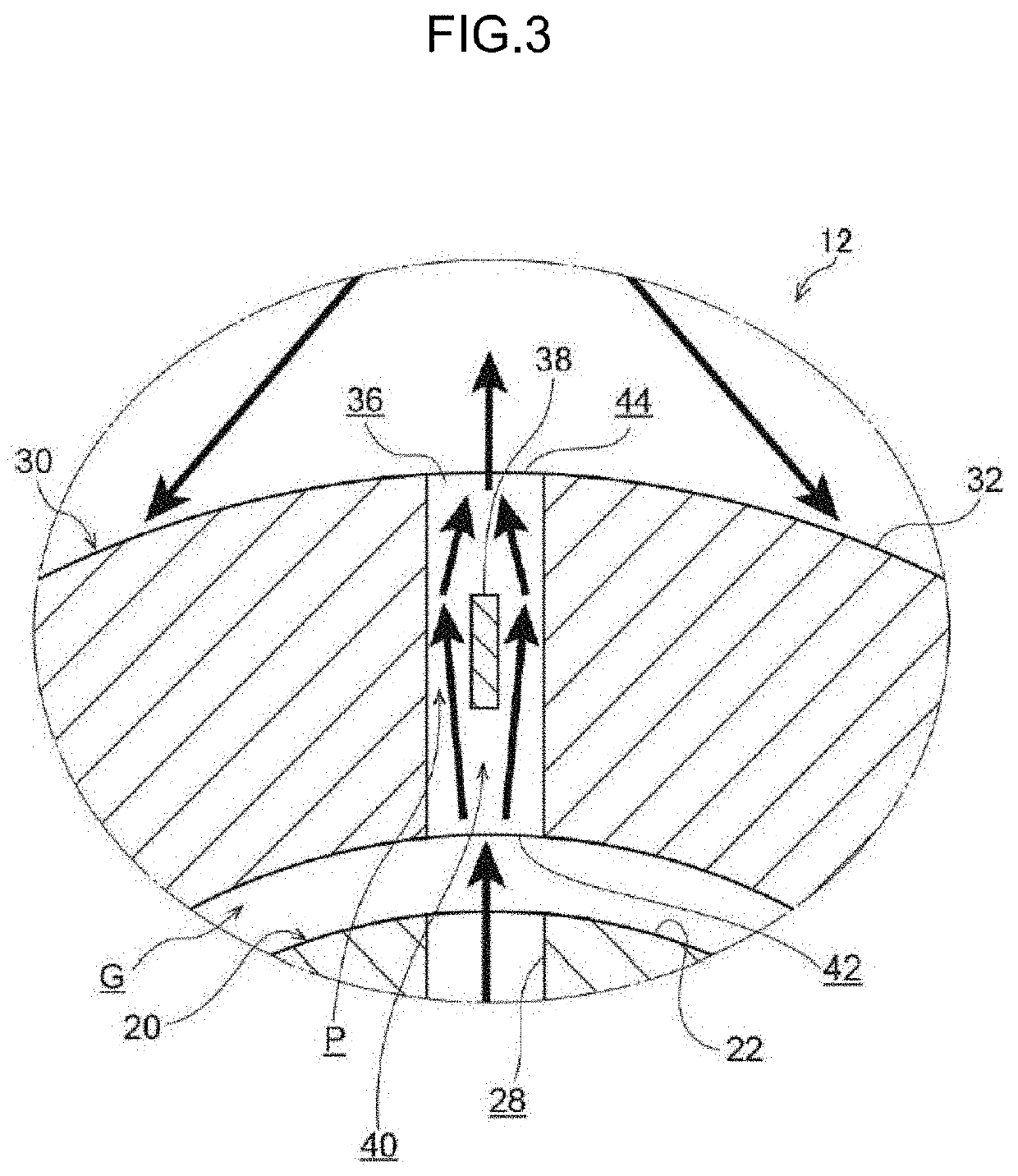
[0031]Also to aid explanation, in FIG. 1, FIG. 3, and FIG. 4, coils 38 are illustrated somewhat smaller than in reality, whereas gaps P between slots 36 and the coils 38 (first flow paths 40 and second flow paths 50) are illustrated larger somewhat than in reality. Also to aid explanation, in FIG. ...


PUM


Abstract

A motor coil cooling structure, includes: a rotor core fixed to a rotation shaft having an internal supply path for coolant, and that includes a rotor-side flow path in communication with the supply path and passing through to a radial direction outer side of the rotor core; a stator core disposed at the rotor core so as to form a space between the stator core and the rotor core, and that includes slots each housing a coil; first flow paths formed so as to include the slots and pass through the stator core in a radial direction; second flow paths formed in an upper portion of the stator core relative to the rotation shaft, including the slots, extending in a radial direction and passing through the stator core only at a radial direction outer circumferential side thereof; and a supply section that supplies coolant from above the stator core.

Description

CROSS-REFERENCE TO RELATED APPLICATION[0001]This application is based on and claims priority under 35 USC 119 from Japanese Patent Application No. 2021-002216 filed on Jan. 8, 2021, the disclosure of which is incorporated by reference herein.BACKGROUNDTechnical Field[0002]The present disclosure relates to a motor coil cooling structure.Related Art[0003]Japanese Patent Application Laid-Open (JP-A) No. 2019-146388 discloses a structure for cooling coils housed in plural slots formed arrayed around a circumferential direction of a stator core of a motor. The motor includes a rotor core capable of rotating integrally with a rotation shaft, and the stator core provided opposing an outer peripheral portion of the rotor core. In the technology disclosed in JP-A No. 2019-146388, slot openings that are in communication with the plural slots extend along a rotation-axial direction at an inner peripheral face of the stator core, and the coils are directly cooled by oil flowing through the slot...

Claims


Application Information

Patent Timeline
Patent Type & Authority Applications(United States)
IPC IPC(8): H02K9/19H02K1/16
CPCH02K9/19H02K1/16H02K1/32H02K1/20H02K3/24H02K1/165
Inventor SAKAMOTO, HIRONOBU
Owner TOYOTA JIDOSHA KK
Why Eureka
Try Eureka