Inductor component

Pending Publication Date: 2022-07-28
MURATA MFG CO LTD
View PDF0 Cites 0 Cited by
  • Summary
  • Abstract
  • Description
  • Claims
  • Application Information

AI Technical Summary

Problems solved by technology

It was found that the loss of the magnetic flux increases due to the interference with the flow of the magnetic flux of the coil, which lowers the acquisition efficiency of the L value and lowers the Q value.
Particularly, when the inductor component becomes small, the width of the wiring part becomes s

Method used


Image

  • Inductor component
  • Inductor component
  • Inductor component

Examples


first embodiment

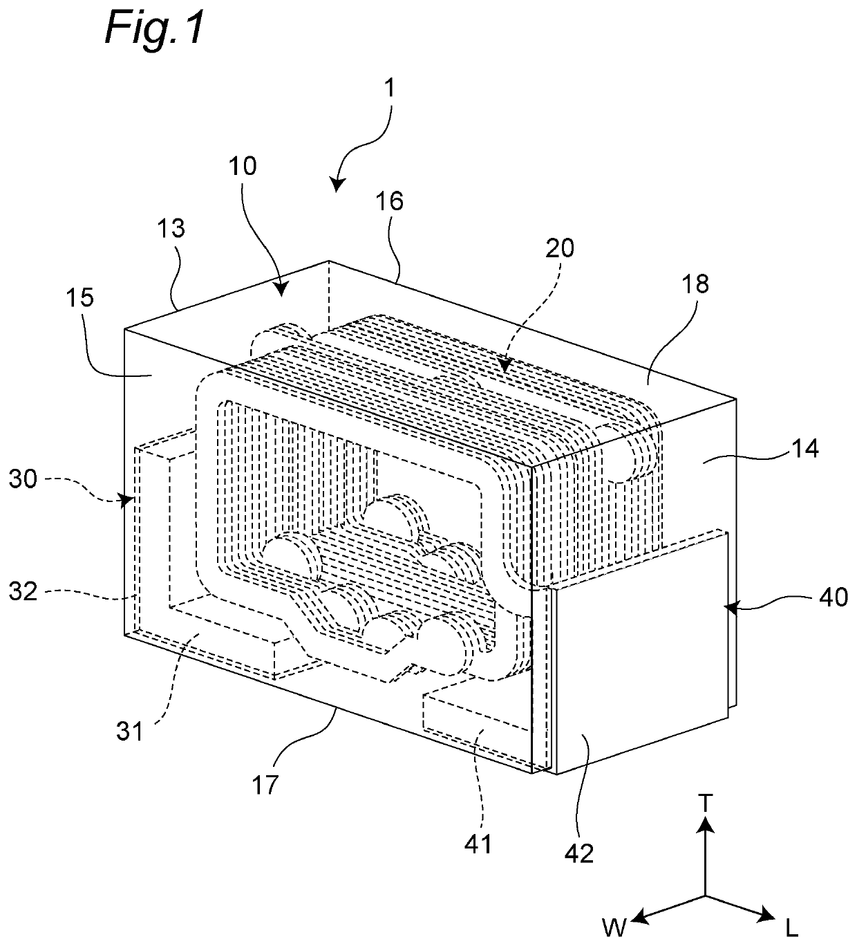
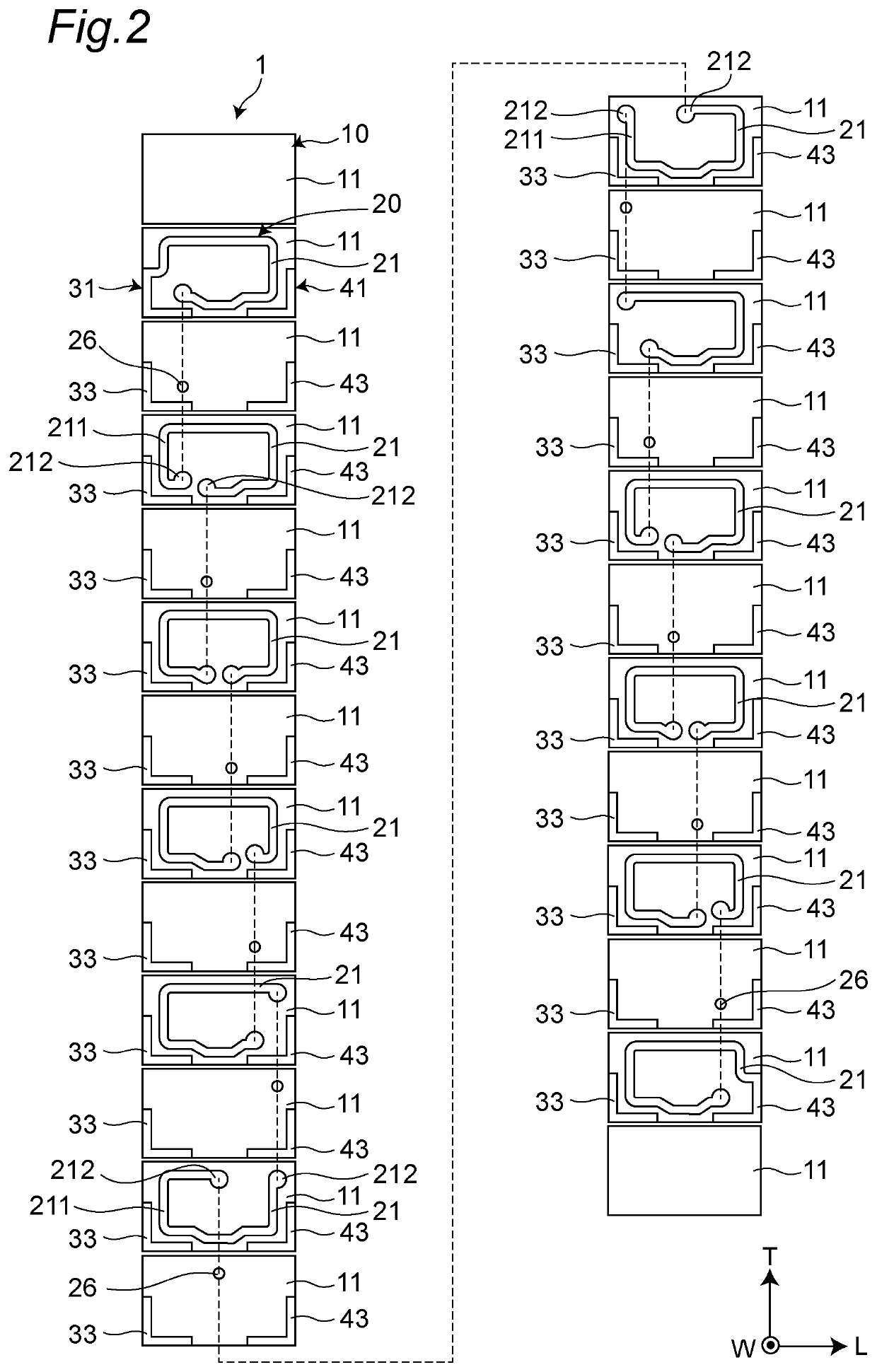
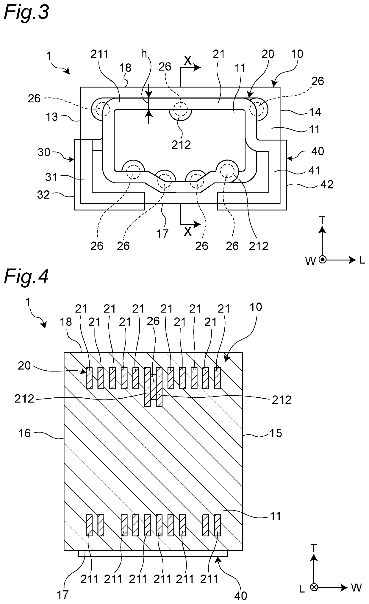
[0079]FIG. 1 is a perspective view showing a first embodiment of an inductor component. FIG. 2 is an exploded view of the inductor component. FIG. 3 is a perspective front view from a first side surface side of the inductor component. FIG. 4 is a cross-sectional view taken along a line X-X of FIG. 3.

[0080]As shown in FIGS. 1 to 4, the inductor component 1 includes an element body 10, a coil 20 disposed in the element body 10, and a first external electrode 30 and a second external electrode 40 disposed on the element body 10 and electrically connected to the coil.

[0081]The inductor component 1 is electrically connected via the first and second external electrodes 30, 40 to a wiring of a circuit board not shown. The inductor component 1 is used as an impedance matching coil (matching coil) of a high-frequency circuit, for example, and is used for an electronic device such as a personal computer, a DVD player, a digital camera, a TV, a portable telephone, automotive electronics, and m...

second embodiment

[0116]FIG. 14 is a cross-sectional view showing a second embodiment of the inductor component. The second embodiment is different in the inner diameter of the coil from the first embodiment. This different configuration will be described below. The other configurations are the same as those of the first embodiment and will not be described. In FIG. 14, the pad parts are omitted for convenience.

[0117]As shown in FIG. 14, in an inductor component 1A of the second embodiment, the inner diameter of the coil 20 increases from the center in the axial direction of the coil 20 toward both ends. Although the inner diameter of the coil 20 increases continuously, the inner diameter may increase stepwise. The width dimension h of the wiring parts 211 of all the coil wirings 21 is the same. Therefore, the outer diameter of the coil 20 increases from the center in the axial direction of the coil 20 toward both ends.

[0118]According to the configuration described above, the inner diameter of the co...

third embodiment

[0132]FIG. 22 is a cross-sectional view showing a third embodiment of the inductor component. The third embodiment is different from the second embodiment in that the pad part is drawn. This different configuration will be described below. The other configurations are the same as those of the second embodiment and will not be described. In the third embodiment, the same reference numerals as those in the first embodiment denote the names of the same members as in the first embodiment.

[0133]As shown in FIG. 22, in an inductor component 1C of the third embodiment, the width dimension h of the wiring parts 211 of all the coil wirings 21 is the same. The first coil wiring 21A corresponds to a portion having a small inner diameter of the coil 20. When viewed in the axial direction, a first protrusion amount e1 from the second wiring part 211B of the first pad part 212A to the outside of the coil 20 is greater than or equal to a second protrusion amount e2 from the second wiring part 211B...


PUM


Abstract

An inductor component comprising an element body; a coil disposed in the element body; and a first external electrode and a second external electrode disposed on the element body and electrically connected to the coil. The coil has a helical structure in which the coil is wound while proceeding along an axis such that the axis is parallel to a bottom surface of the element body and intersects with first and second side surfaces of the element body. The coil includes coil wirings laminated along the axis and wound along a plane, and a via wiring connecting the coil wirings. The first coil wiring is on a central side in the axial direction of the coil relative to the second coil wiring, and a first pad part of the first coil wiring is adjacent to a second wiring part of the second coil wiring in the axial direction.

Description

CROSS REFERENCE TO RELATED APPLICATION[0001]This application claims benefit of priority to Japanese Patent Application 2021-009560, filed Jan. 25, 2021, the entire content of which is incorporated herein by reference.BACKGROUNDTechnical Field[0002]The present disclosure relates to an inductor componentBackground Art[0003]A conventional inductor component is described in Japanese Laid-Open Patent Publication No. 2015-015297. This inductor component includes an element body and a coil disposed in the element body. The coil has multiple coil wirings laminated along the axis of the coil and via wirings connecting the multiple coil wirings. The coil wiring has a wiring part and a pad part disposed at an end portion of the wiring part and connected to the via wiring.SUMMARY[0004]In the connection between the coil wiring and the via wiring, it is necessary to ensure an area of contact of the via wiring with the coil wiring (i.e., the cross-sectional area of the via wiring) so as to prevent...

Claims


Application Information

Patent Timeline
IPC IPC(8): H01F27/28
CPCH01F27/2804H01F27/292H01F27/34H01F2027/2809H01F17/0013
Inventor TAKAMATSU, TSUYOSHIYOSHINAKA, KEIICHIMATSUNAGA, MINORU
Owner MURATA MFG CO LTD
Why Eureka
Try Eureka