
Filter device

Pending Publication Date: 2022-07-28
MITSUBISHI ELECTRIC CORP
View PDF0 Cites 0 Cited by
  • Summary
  • Abstract
  • Description
  • Claims
  • Application Information

AI Technical Summary

Benefits of technology

The present patent provides a filter device that can delay and multiply input signals with a filter coefficient and adjust the result using a coefficient adjuster. This can help to accurately filter the signals and achieve the desired output signals. The technical effect is an improved filtering process for signals.

Problems solved by technology

In digital filters, quantization noise and computation error have been known to be a cause for deterioration in filter characteristics.
The quantization noise has a problem that the noise increases as the length of a filter increases.
That is, the computation error cannot be satisfactorily reduced.

Method used


Image

  • Filter device
  • Filter device
  • Filter device

Examples


first embodiment

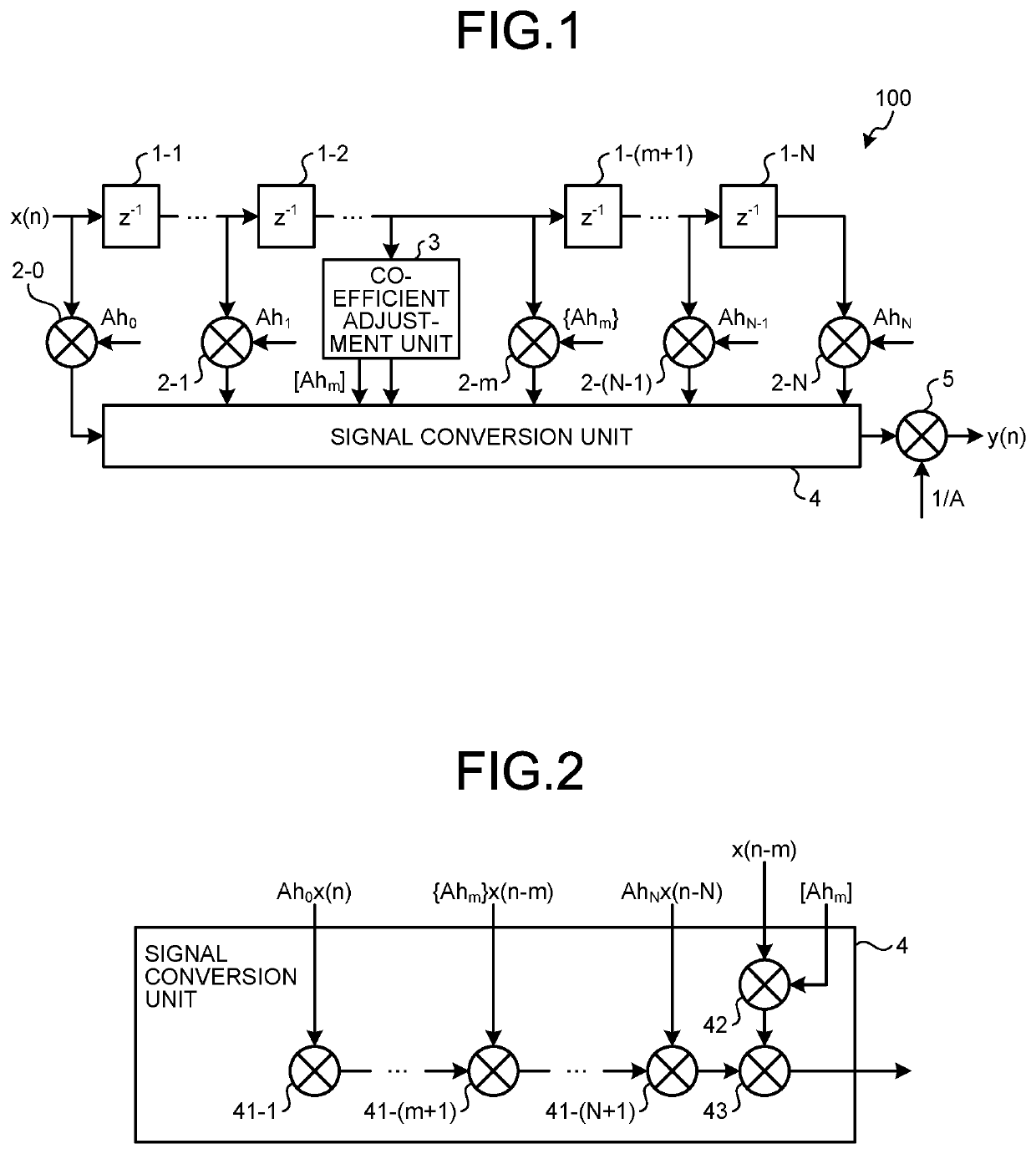
[0016]FIG. 1 is a diagram illustrating an exemplary circuit configuration of a filter device according to the first embodiment of the present disclosure. The filter device 100 according to the first embodiment is a digital filter, specifically, an FIR filter. In a case where the filter device 100 is implemented by dedicated hardware, the filter device 100 is realized by, for example, a single circuit, a composite circuit, a programmed processor, a parallel programmed processor, an application specific integrated circuit (ASIC), a field programmable gate array (FPGA), or any combination thereof.

[0017]As illustrated in FIG. 1, the filter device 100 includes a plurality of delay units or delayers 1-1 to 1-N that delay an n-bit input signal by a predetermined time, multiplication units or multipliers 2-0 to 2-N that multiply an input signal to the filter device 100 and delayed signals that are signals respectively outputted from the delay units 1-1 to 1-N by filter coefficients correspo...

second embodiment

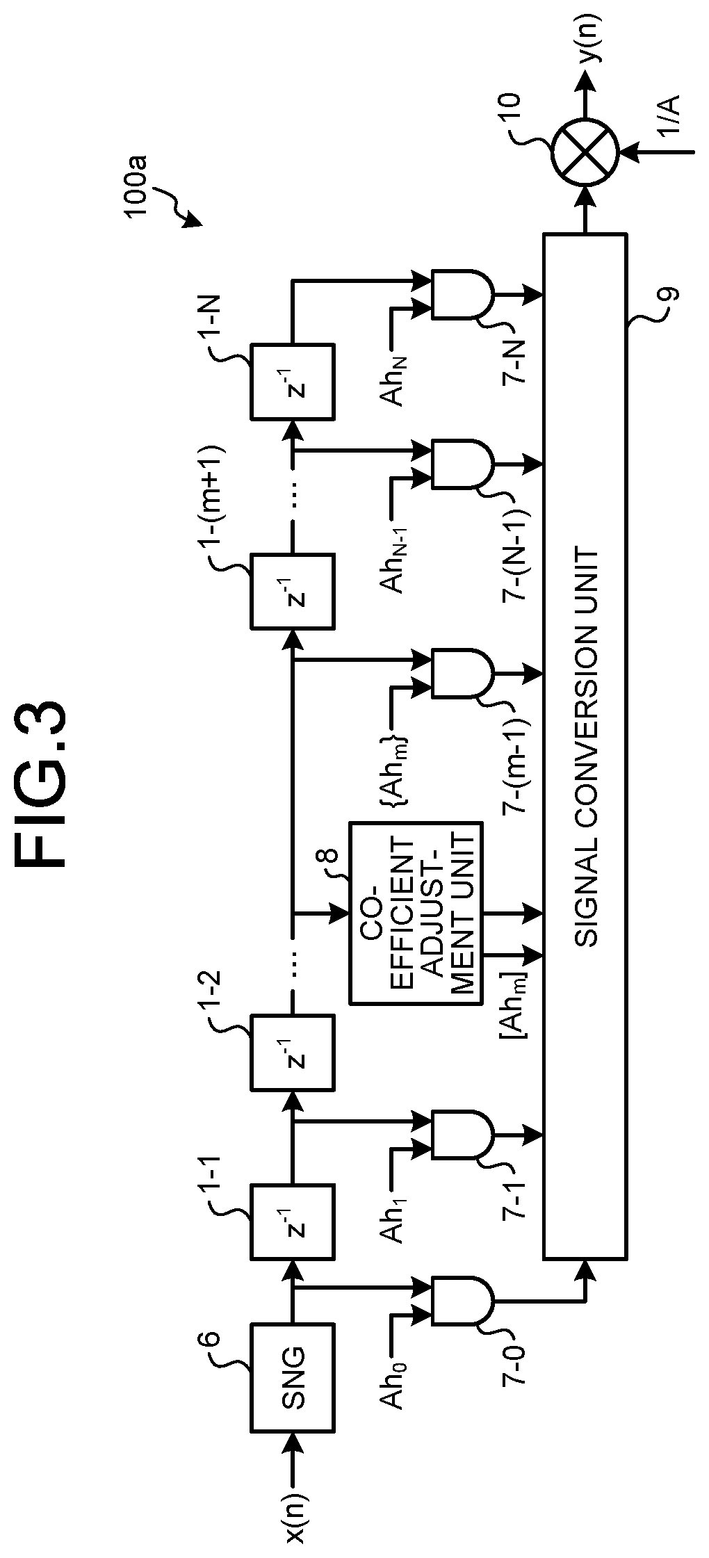
[0029]Next, the filter device according to the second embodiment, specifically, the filter device implemented using stochastic computing will be described.

[0030]Stochastic computing is disclosed, for example, in the literature “Warren J. Gross and Vincent C. Gaudet Editors, ‘Stochastic Computing: Techniques and Applications’”.

[0031]Stochastic computing is characterized by its effectiveness in reducing the circuit scale of product-sum operation, and the filter device can be downsized by being configured using stochastic computing. In other hand, in stochastic computing, a numerical value is expressed by the existence probability of zero and one in a bitstream generated using a random number sequence, so that the correlation in the random number sequence between numerical values inputted to the computing circuit becomes a cause of the computation error. Reducing this computation error is the problem to be considered when stochastic computing is used.

[0032]FIG. 3 is a diagram illustrat...

third embodiment

[0043]In the filter device of a configuration according to the second embodiment, errors in stochastic representation are classified as conversion errors derived from conversion into stochastic representation and correlation errors derived from the correlation between random number sequences used for converting each input into stochastic representation during computation. The present embodiment describes a configuration for reducing a conversion error and a correlation error.

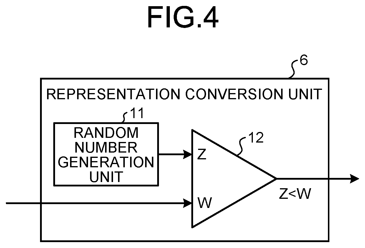
[0044]The conversion error occurs when a random number sequence is biased. For example, suppose that the representation conversion unit 6 of FIG. 4 expresses the range of 0 to 1 by stochastic representation with the SN length of 10. In this case, in order to convert the value 0.6 into stochastic representation, it is desirable that the random number generation unit 11 outputs uniform values, for example, 6 values that are each smaller than or equal to 0.6 and 4 values that are each larger than 0.6. However, the ...


PUM


Abstract

A filter device includes: delay units serially connected to delay an input signal and output a delayed signal; multiplication units multiplying the delayed signal by a filter coefficient based on a predetermined value and a multiplying factor adjustment value; a coefficient adjustment unit that, when a multiplication result obtained by multiplying the predetermined value by the multiplying factor adjustment value exceeds a maximum value of a filter-coefficient representation range, divides the multiplication result exceeding the maximum value by the maximum value, and outputs a quotient of division as a coefficient adjustment value; a signal conversion unit outputting a signal obtained by adding after-filter-coefficient-multiplication signals outputted by the multiplication units and an adjusted signal obtained by adjusting a corresponding delayed signal using the coefficient adjustment value; and a division unit generating an output signal by dividing the signal outputted by the signal conversion unit by the multiplying factor adjustment value.

Description

CROSS-REFERENCE TO RELATED APPLICATION[0001]This application is a continuation application of International Application PCT / JP2019 / 049224, filed on Dec. 16, 2019, and designating the U.S., the entire contents of which are incorporated herein by reference.BACKGROUND OF THE INVENTION1. Field of the Invention[0002]The present disclosure relates to a filter device that filters a digital signal.2. Description of the Related Art[0003]A finite impulse response filter (hereinafter referred to as an FIR filter) is a kind of a digital filter, which convolves an input signal with filter coefficients and outputs a resultant signal obtained by the convolution.[0004]In digital filters, quantization noise and computation error have been known to be a cause for deterioration in filter characteristics.[0005]The quantization noise has a problem that the noise increases as the length of a filter increases. Regarding this problem, Japanese Patent Application Laid-open No. H3-46813 describes an inventiv...

Claims


Application Information

Patent Timeline
IPC IPC(8): H03H17/02G06F7/52
CPCH03H17/0227H03H2017/0081G06F7/52H03H17/06H03H17/0219H03H2017/022H03H17/0233H03H17/023H03H2218/02
Inventor YAMASHITA, YASUTAKATANI, SHIGENORIKANEKO, KAZUMAUCHIDA, SHIGERU
Owner MITSUBISHI ELECTRIC CORP
Learn More