

Cellulose-based structural flooring panel assembly
- Summary
- Abstract
- Description
- Claims
- Application Information
AI Technical Summary
Benefits of technology
Problems solved by technology
Method used
Image

Examples
Embodiment Construction
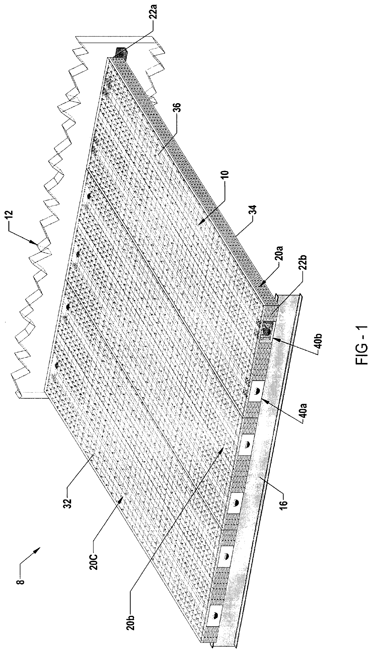
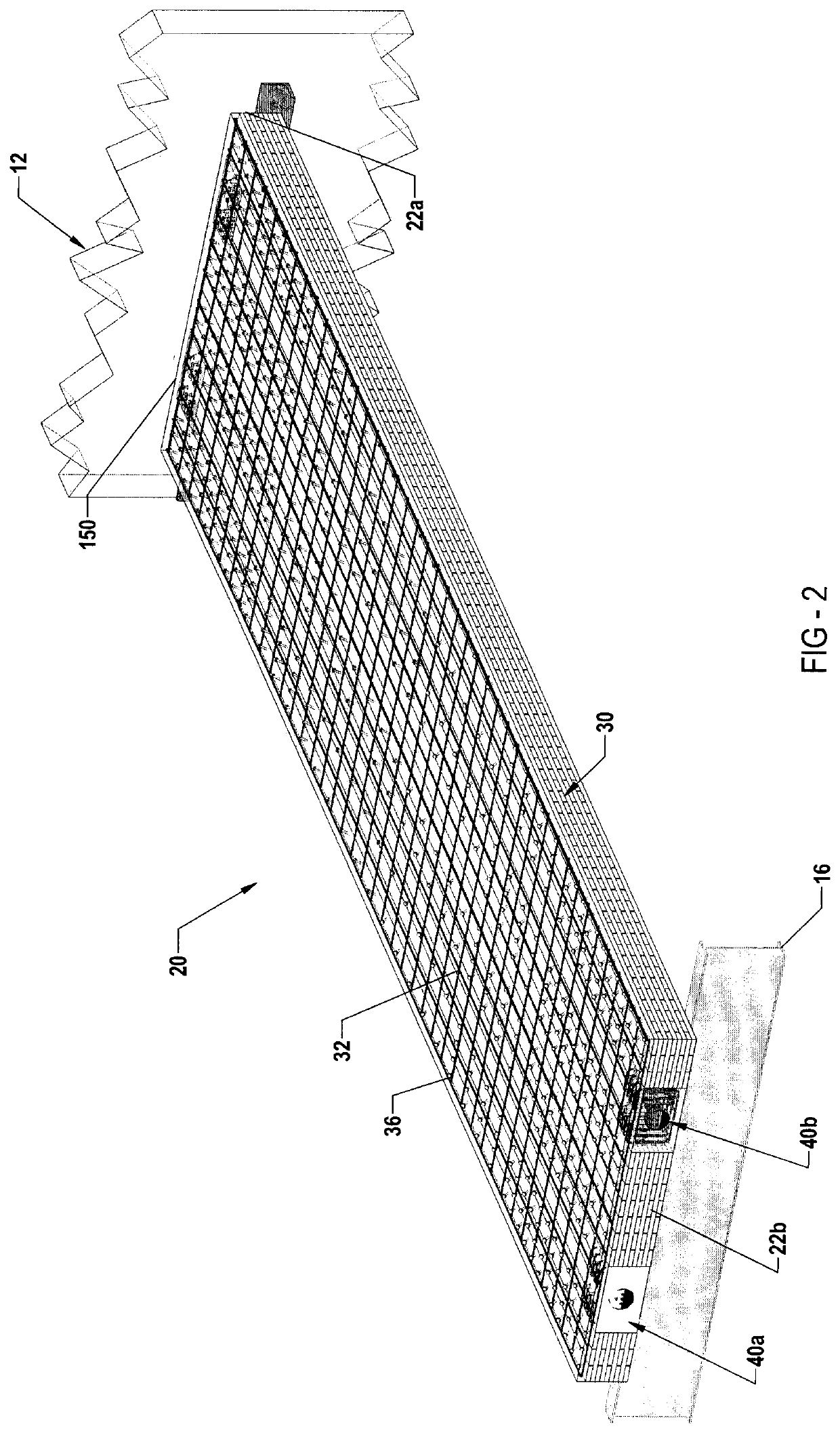
[0051]Reference is made to FIG. 1 which illustrates a partial cut-away view of a Class A high-rise building 8 which has a building floor 10 formed using a number of structural flooring panel assemblies 20a, 20b, 20c; and which are overlaid by a top concrete layer 36. As will be described, each of the flooring panel assemblies 20a, 20b and 20c is preferably pre-manufactured off-site as at least a partially pre-manufactured unit. The flooring panel assemblies 20 are delivered substantially ready for installation, in a substantially unsupported position spanning between the building elevator core 12 and the outermost building perimeter support wholly, such as a peripherally extending I-beam support 16, or other such steel or concrete structure.
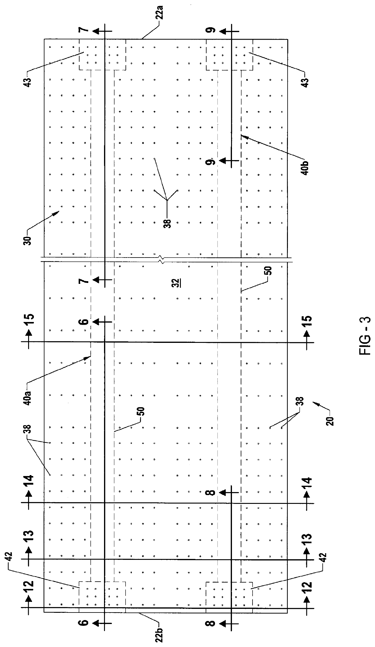
[0052]FIG. 1 illustrates each flooring panel assembly 20a, 20b, 20c as each being generally rectangular, and extending longitudinally from respective innermost first end 22a which are fixedly coupled to the building core 12, to outermost second e...
PUM
 Abstract
Description
Claims
Application Information