Seat sliding device and slide lever connecting structure in the seat sliding device

a technology of sliding device and connecting structure, which is applied in the direction of movable seats, vehicle components, vehicle arrangements, etc., to achieve the effect of easy and sure connection, less rattling, and easy and sure connection

Pending Publication Date: 2022-08-11
DELTA KOGYO CO LTD
View PDF0 Cites 0 Cited by
  • Summary
  • Abstract
  • Description
  • Claims
  • Application Information

AI Technical Summary

Benefits of technology

[0027]According to the present invention, the connecting end part of the slide lever has a tubular shape and the front end part of the release lever is inserted in the connecting end part with the connection spring member therebetween. The connection spring member is formed of a worked wire for springs and has the bent end located forward and the wire parts extending rearward from the bent end. The protruding engagement parts are formed in the wire parts. In the state in which the wire parts are placed inside the front end part of the release lever with the protruding engagement parts protruding from the engagement protrusion holes of the release lever in advance, the tubular connecting end part of the slide lever is fitted on the outer side of the release lever. The connection can be easily done by the protruding engagement parts of the connection spring member engaging with the engagement holes of the slide lever. Further, the protruding engagement parts engage with both the engagement protrusion holes of the release lever and the engagement holes of the slide lever, and the front lock part including the bent end located forward is locked with its acting end pressing the inner surface of the connecting end part of the slide lever. This enables the easy and sure connection of the slide lever and the release lever.
[0028]Further, the entire connection spring member is formed of the wire material for springs, and the wire parts between the protruding engagement parts and the front lock part are not fixed to the inner surface of the slide lever. Therefore, elasticity corresponding to the length from the protruding engagement parts to the bent end is exhibited. If the wire parts between the protruding engagement parts and the front lock part are fixed to some place, the spring constant becomes high because actually functioning elasticity corresponds to that of a spring shorter than the length of the wire parts, but in the connecting structure of the present invention, this does not occur, and the elasticity of the connection spring member functions with the spring constant corresponding to the length of the wire parts between the protruding engagement parts and the front lock part. This makes it possible not only to easily and surely connect the slide lever and the release lever with less rattling therebetween but also to absorb even a slight impact occurring at the locking operation time of the lock plate, achieving a higher effect of reducing the generation of abnormal noise.

Problems solved by technology

However, in the state of being interposed between the slide lever and the release lever, the tubular spring is integrated with the inner surface of the slide lever and the elasticity of a tubular main body of the tubular spring does not act much, and the elasticity of the inwardly raised pieces and the outwardly raised pieces protruding from the tubular main body mainly acts.

Method used


Image

  • Seat sliding device and slide lever connecting structure in the seat sliding device
  • Seat sliding device and slide lever connecting structure in the seat sliding device
  • Seat sliding device and slide lever connecting structure in the seat sliding device

Examples


Embodiment Construction

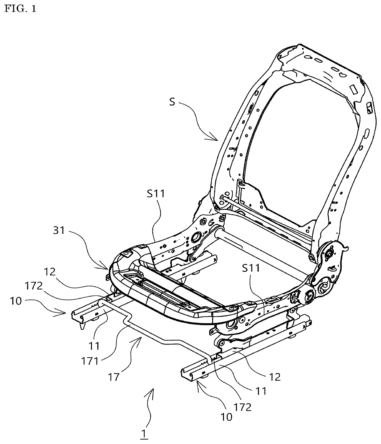
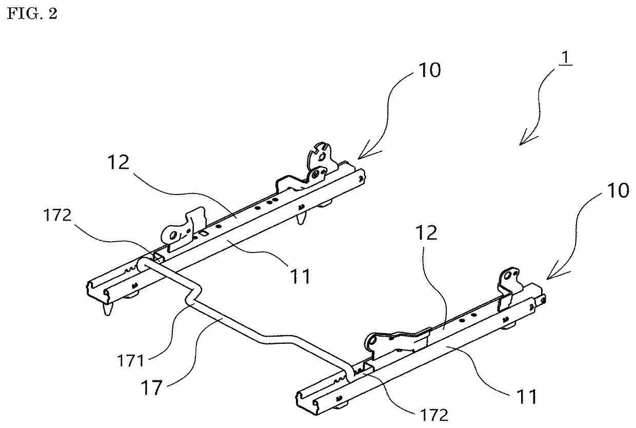
[0036]The present invention will be hereinafter described in more detail based on an embodiment illustrated in the drawings. As illustrated in FIG. 1, a seat frame S is provided such that its forward and rearward sliding can be adjusted by a pair of left and right seat sliding devices 1 of this embodiment that are a predetermined interval apart from each other in the width direction of the vehicle body. A slide lever 17 extending between left and right seat slide adjusters 10, 10 included in the seat sliding device 1 is provided below a front edge of a seat cushion frame S1. The slide lever 17 connects later-described release levers 161, 161 of locking mechanisms 16, 16 provided in the left and right seat slide adjusters 10, 10, and the locking is released when the slide lever 17 is operated by a person.

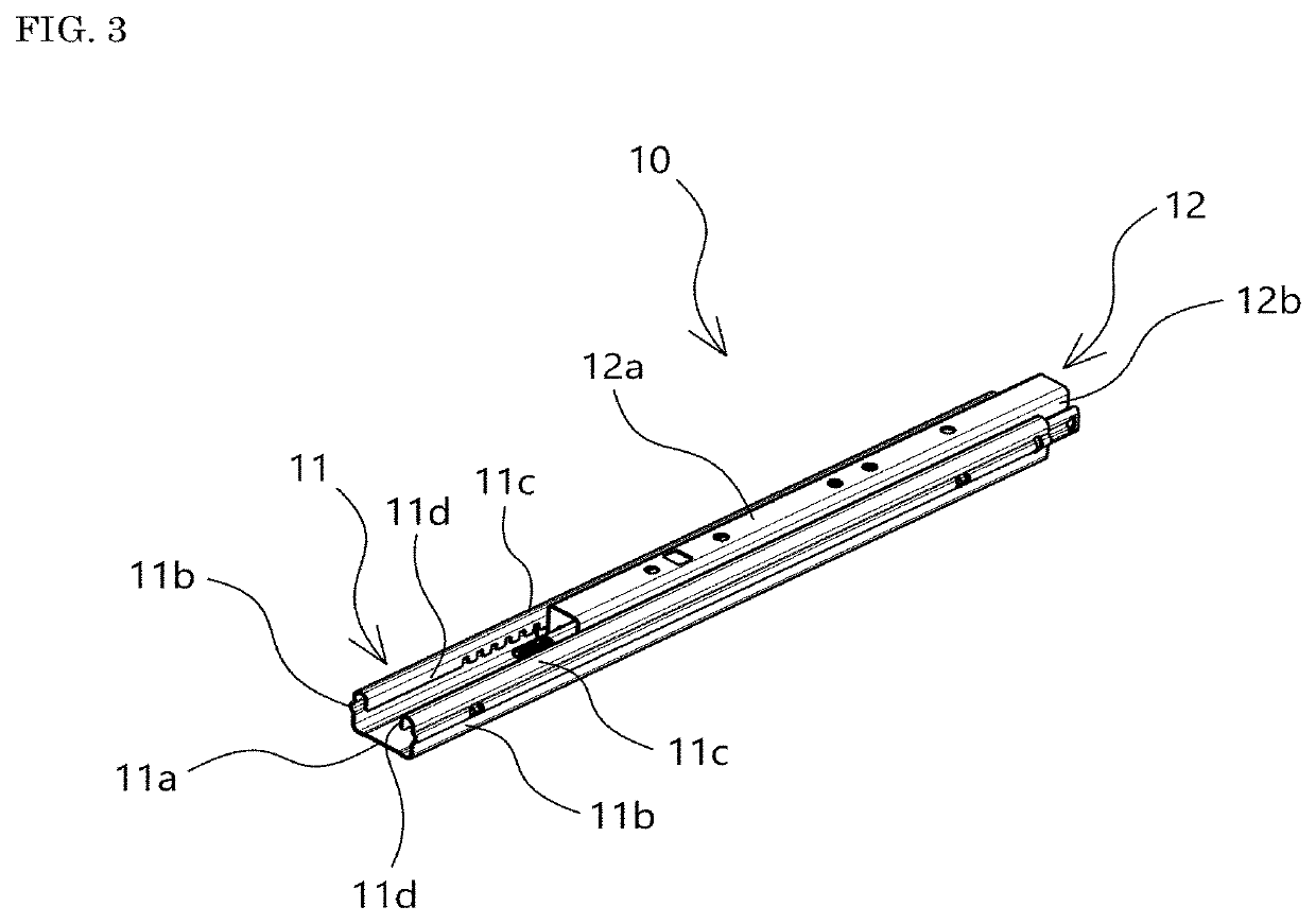
[0037]In the following, with reference to mainly FIG. 3 to FIG. 6 which illustrate only one of the seat slide adjusters 10, 10, its detailed structure will be described, but the lef...


PUM


Abstract

To reduce rattling between a slide lever and a release lever and abnormal noise. A connecting end part (172) of a slide lever (17) has a tubular shape, and a front end part (161a) of a release lever (161) is inserted in the connecting end part (172) with a connection spring member (180) therebetween. The connection spring member (180) is formed of a worked wire material for springs and has a bent end (181a) located forward and wire parts (181) extending rearward from the bent end (181a). Protruding engagement parts (183) are formed in the wire parts (181). The wire parts (181) are placed inside the front end part (161a) of the release lever (161), and the protruding engagement parts (183) are made to protrude from engagement protrusion holes (161e) of the release lever (161) in advance, and then the tubular connecting end part (172) of the slide lever (17) is fitted on the outer side of the front end part (161a). The protruding engagement parts (183) of the connection spring member (180) engage with engagement holes (172b) of the slide lever, and at the same time, its front lock part (182) presses the inner surface of the connecting end part (172).

Description

TECHNICAL FIELD [0001]The present invention relates to a seat sliding device used in seats of vehicles such as automobiles, airplanes, trains, ships, and buses and a slide lever connecting structure in the seat sliding device. BACKGROUND ART [0002]A seat sliding device includes: a lower rail attached to the floor of a vehicle; an upper rail slidably provided on the lower rail and connected to a seat frame; and a pair of left and right seat slide adjusters each having a locking mechanism for fixing the front and rear sliding positions of the upper rail. The locking mechanisms each include: a lock plate having engagement holes or the like which engage with teeth formed in the lower rail; a locking spring member which biases the lock plate in an engagement direction; and a release lever which is linked to the lock plate to operate the lock plate in a disengagement direction against the elastic force of the locking spring member. The seat sliding device further includes a slide lever co...

Claims


Application Information

Patent Timeline
Patent Type & Authority Applications(United States)
IPC IPC(8): B60N2/08
CPCB60N2/08B60N2/0705B60N2/0818B60N2/085
Inventor UMEZAKI, KIYONORITSUCHIYA, KENTA
Owner DELTA KOGYO CO LTD
Why Eureka
Try Eureka