Wire Mounting Solutions

a technology of wire mounting and solution, which is applied in the direction of covering/lining, construction, building components, etc., can solve the problems of high cost of system fabrication, assembly and installation, and water intrusion risk, and achieve the effect of reducing the risk of direct thermal bridging

Pending Publication Date: 2022-08-11
SIMONSEN DAVID JOHN
View PDF0 Cites 1 Cited by
  • Summary
  • Abstract
  • Description
  • Claims
  • Application Information

AI Technical Summary

Problems solved by technology

These methods are either very labor intensive, provide unpredictable results when adhesives are used, or which cause the need for penetrations through the weather barrier which poses risks for water intrusion and direct thermal bridging.
All of these systems are expensive to fabricate, assemble and install so creating a real need to develop an insulation and façade mounting system that satisfies or surpasses all structural requirements for use in all applications such as seismic, of which very few facades have passed, and includes hurricane conditions alongside expected static and dynamic loads associated with commercial buildings.

Method used


Image

  • Wire Mounting Solutions
  • Wire Mounting Solutions
  • Wire Mounting Solutions

Examples


Embodiment Construction

[0066]Various aspects of the present application will evolve from the following detailed description of the preferred embodiments thereof which should be taken in conjunction with the prior described drawings.

[0067]Embodiments of the invention are identified by an upper case letter with an additional upper case letter of the same kind for a variation of the embodiment. Elements of the invention are identified by reference character 10.

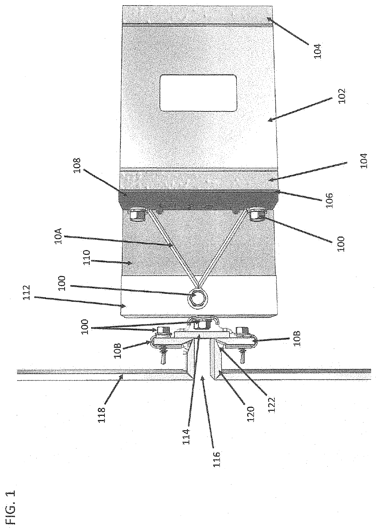
[0068]With reference to FIG. 1, it can be seen that a preferred embodiment of clip wire 10A and frame wire 10B are shown in a full wall assembly. Sheathing 104 is mounted to steel stud 102 on the interior and exterior of the building, with weather barrier 106 is self-adhered to the exterior sheathing 104. Clip wire 10A is mounted over isolator 108 and fastened to steel stud 102 via fasteners 100. Sub-girt 112 is planed and leveled prior to being secured to clip wire 10A via fastener 100. Insulation 110 is then placed between a series of like mounted cl...


PUM


Abstract

Wire Mounting Solutions providing low embodied carbon insulation and façade mounting systems having unmatched thermal and acoustic performance, high structural strengths, and better able to withstand seismic and hurricane activity where other mounting systems may fail due to being too rigid.

Description

CROSS REFERENCES TO RELATED APPLICATIONS[0001]The present application claims the benefit of U.S. Provisional Patent Application Ser. No. 63 / 087,295 filed Oct. 4, 2020.BACKGROUND OF THE INVENTION[0002]The present invention relates to novel and useful products and methods for mounting rigid insulation and facades to buildings utilizing formed steel wires which are much less expensive and difficult to use than traditional materials and methods, and include everything from the weather barrier to the exterior of the façade system on the building envelope.[0003]There have been many ways to mount insulation to the exterior of commercial buildings including friction fitting the insulation batts between thermal clips and then screwing them to the wall with long screws and plastic caps, using adhesive applied stick pins and lock washers, and using thermally broken pins and lock washers. These methods are either very labor intensive, provide unpredictable results when adhesives are used, or wh...

Claims


Application Information

Patent Timeline
Patent Type & Authority Applications(United States)
IPC IPC(8): E04F13/08E04B1/76
CPCE04F13/0821E04F13/0875E04F13/0805E04B1/7629
Inventor SIMONSEN, DAVID JOHN
Owner SIMONSEN DAVID JOHN
Why Eureka
Try Eureka