
Power tool attachment part

Pending Publication Date: 2022-08-18
ATLAS COPCO INDAL TECHN
View PDF0 Cites 0 Cited by
  • Summary
  • Abstract
  • Description
  • Claims
  • Application Information

AI Technical Summary

Benefits of technology

The technical effect of this patent is to provide an attachment part that solves or at least reduces problems of the prior art.

Problems solved by technology

Power tool attachment parts are generally used in confined spaces where it is not possible to use an ordinary power tool to access a bolt or nut of the joint to be tightened.
The internal measurement in the power tool may however not provide an accurate measurement of the torque that the power tool attachment part attached to the power tool is being subjected to.

Method used


Image

  • Power tool attachment part
  • Power tool attachment part

Examples


Embodiment Construction

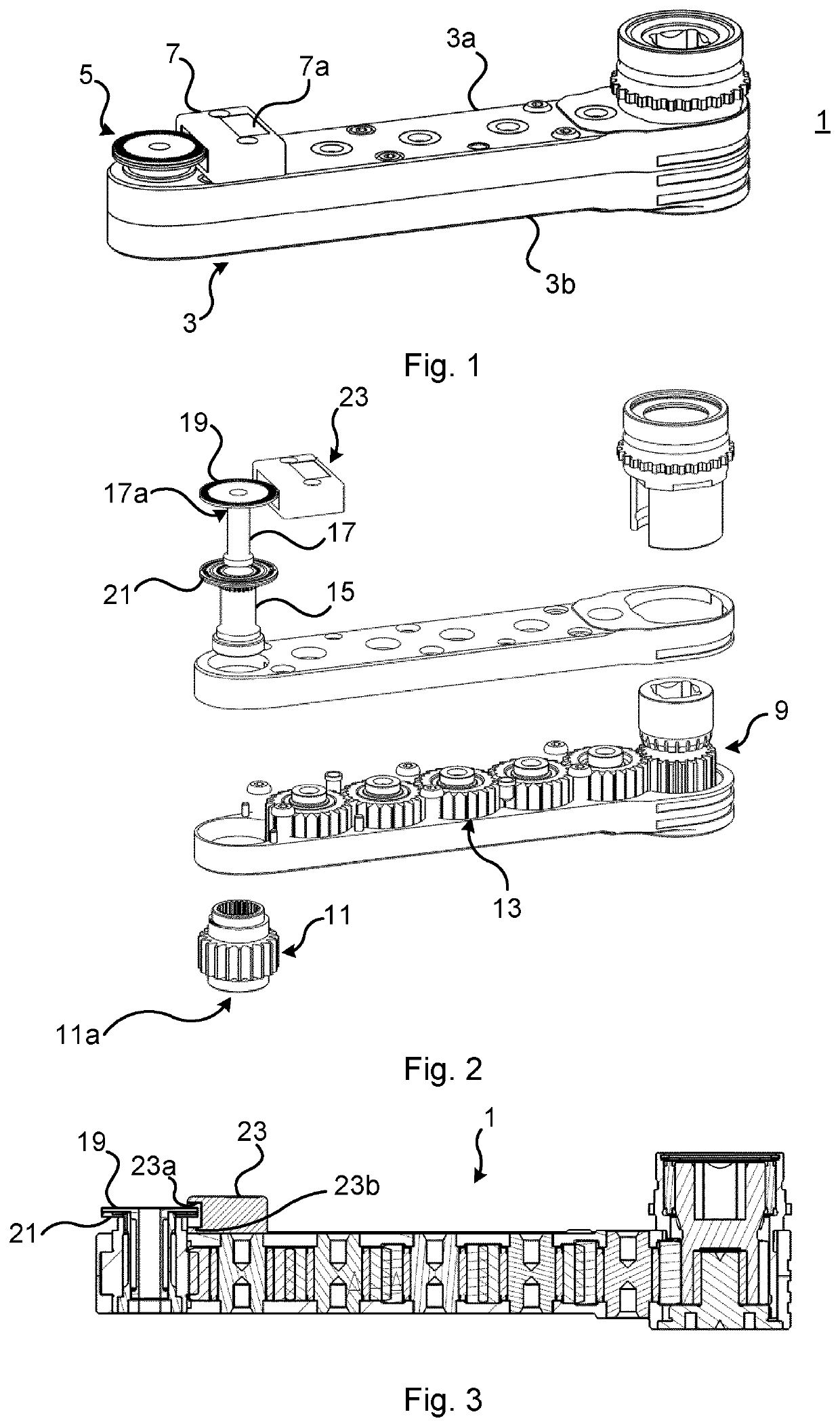
[0037]FIG. 1 depicts an example of a power tool attachment part 1 for a power tool. The power tool may for example be a wrench or a nut runner.

[0038]The exemplified power tool attachment part 1 is a crowfoot. The power tool attachment part 1 comprises an elongate housing 3. The elongate housing 3 comprises an upper housing part or first housing part 3a and a lower housing part or second housing part 3b. The upper housing part 3a is interconnected with the lower housing part 3b.

[0039]FIG. 2 shows the power tool attachment part 1 in an exploded view. The power tool attachment part 1 comprises an input gear wheel 9 and an output gear wheel 11 arranged in the elongate housing 3. The input gear wheel 9 is arranged at a first end of the elongate housing 3. The output gear wheel 9 is arranged at a second end of the housing 3.

[0040]The power tool attachment part 1 furthermore comprises one or more intermediate gear wheels 13. The input gear wheel 9 is drivingly connected to the output gear...


PUM


Abstract

A power tool attachment part for a power tool, comprising: an elongate housing including an upper housing part and a lower housing part interconnected with the upper housing part, an input gear wheel configured to be connected to an output shaft of a power wrench, which input gear wheel is arranged at a first end of the housing, an output gear wheel with an output connection, which output gear wheel is arranged at a second end of the housing, an intermediate gear wheel arranged inside the housing and configured to transmit rotation of the input gear wheel to the output gear wheel, a socket arranged concentrically with and radially inside the output gear wheel, and a torque sensor configured to measure the strain on the socket and thereby obtain a measure of the torque at the output gear wheel.

Description

CROSS-REFERENCE TO RELATED APPLICATIONS[0001]This application is a National Stage Patent Application (filed under 35 § U.S.C. 371) of PCT / EP2020 / 068946, filed Jul. 6, 2020 of the same title, which, in turn claims priority to Swedish Patent Application No. 1930254-6 filed Jul. 24, 2019 of the same title; the contents of each of which are hereby incorporated by reference.FIELD OF THE INVENTION[0002]The present disclosure relates to a power tool attachment part for a power tool.BACKGROUND OF THE INVENTION[0003]Power tool attachment parts are generally used in confined spaces where it is not possible to use an ordinary power tool to access a bolt or nut of the joint to be tightened. A power tool attachment part is also known as a crowfoot, a front part attachment or an offset attachment.[0004]A power tool attachment part includes a plurality of gear wheels that transmit a rotating movement from an input gear wheel to an output gear wheel. The gear wheels are generally located in a row, ...

Claims


Application Information

Patent Timeline
IPC IPC(8): B25B23/147B25B21/00
CPCB25B23/147B25B23/1425B25B21/002B25B17/00B25B21/00B25B13/48B25B23/142B25B13/481
Inventor RADIF, NABIL KHALILERIKSSON, ULF MIKAEL
Owner ATLAS COPCO INDAL TECHN
Learn More