Air receiver for solar power plant

a solar power plant and receiver technology, applied in the field of solar power plant air receivers, can solve the problems of inability to provide energy at all times, inability to use solar energy for industrial scale applications, and inefficient and ineffective capture of sun and solar energy conversion

Pending Publication Date: 2022-08-18
HELIOGEN HLDG INC
View PDF0 Cites 0 Cited by
  • Summary
  • Abstract
  • Description
  • Claims
  • Application Information

AI Technical Summary

Problems solved by technology

However, existing solar energy systems have various drawbacks that make them inefficient and ineffective for capturing energy from the Sun and converting it to energy for use on an industrial and utility scale.
One such drawback is the inability to provide energy at all times (e.g., at nighttime).
Another drawback is the inability to use solar energy for industrial scale applications.

Method used


Image

  • Air receiver for solar power plant
  • Air receiver for solar power plant
  • Air receiver for solar power plant

Examples


Embodiment Construction

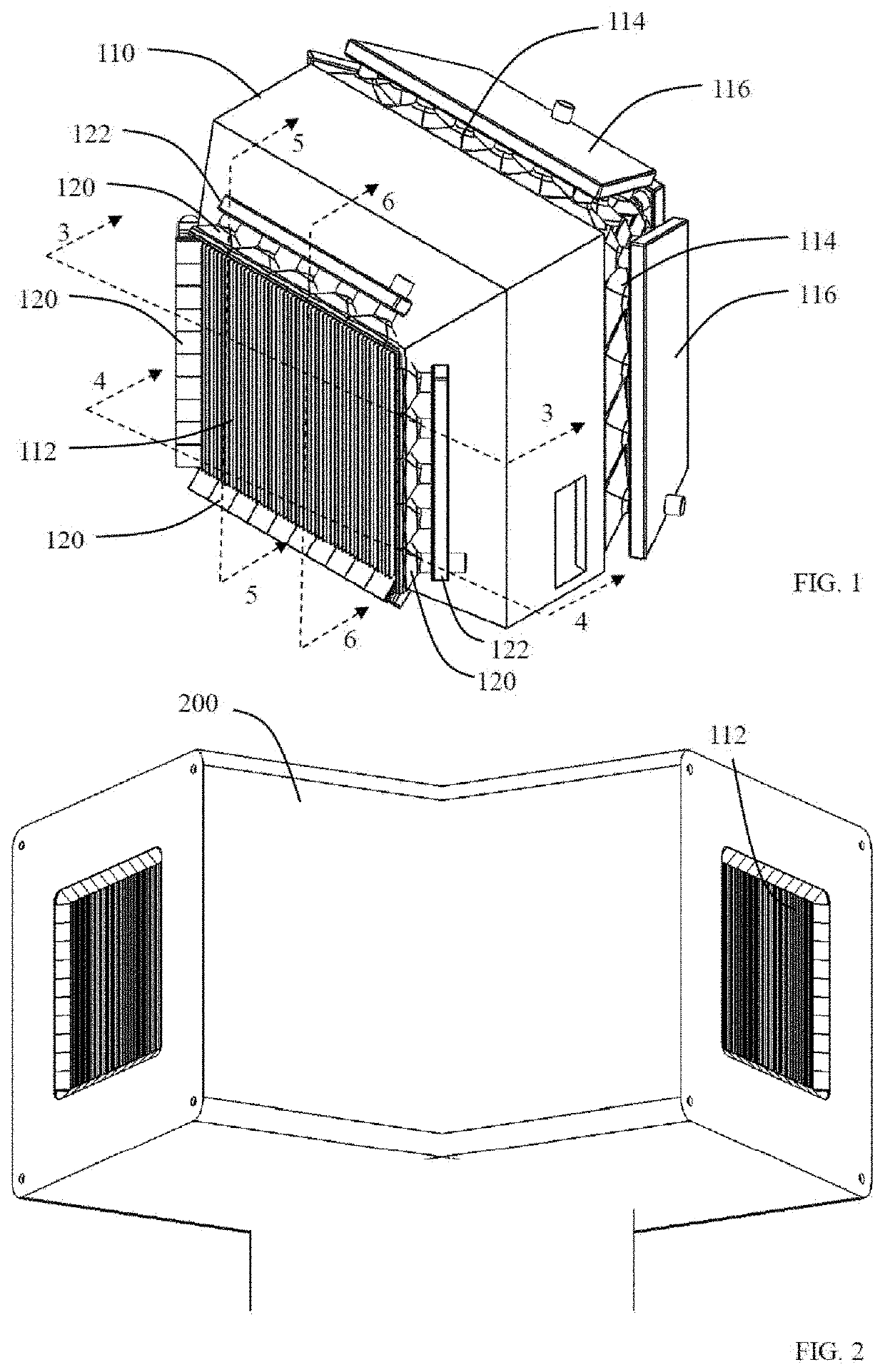
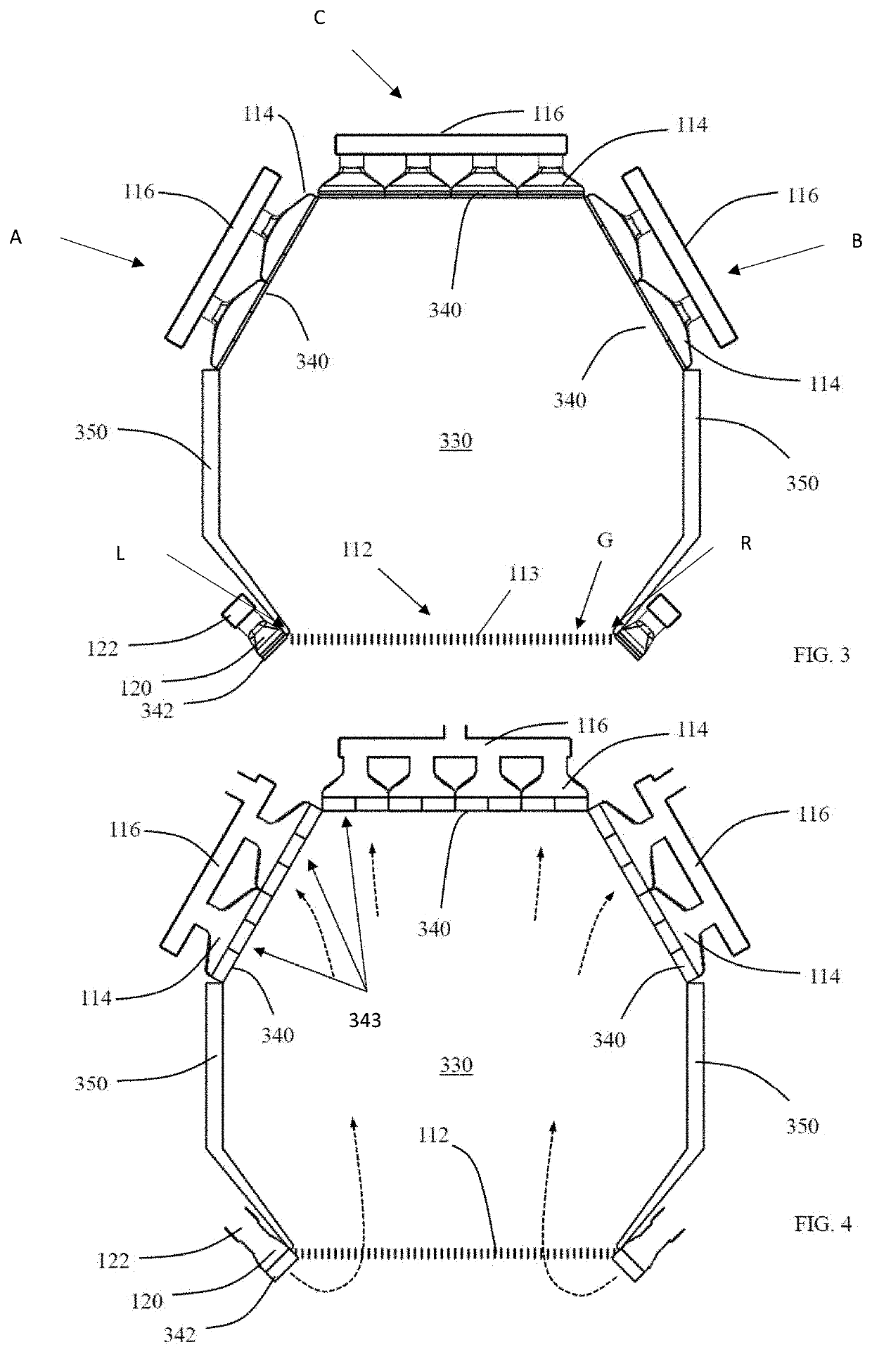
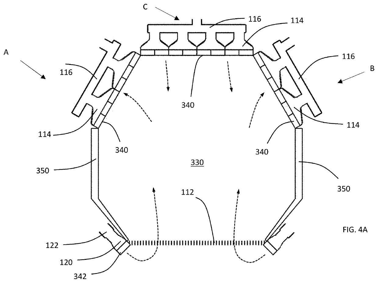
[0023]Described below is a novel air receiver for use in a solar power plant, such as in a power tower of a solar power plant. Illustrated in FIG. 1 is a perspective view of an air receiver 110. The air receiver 110 can receive sunlight and convert that sunlight to heat. The air receiver 110 includes an aperture 112 that receives sunlight that is aimed at the receiver, a plurality of output ports 114 via which heated air (e.g., generated in) the receiver is captured, and at least one output manifold 116 that channeling the heated air away from the receiver 110. The air receiver 110 further includes input ports 120 via which pre-heated air is introduced into the receiver and input manifolds 122 that direct the preheated air to the input ports 120.

[0024]As illustrated in FIG. 1, in one implementation the input ports 120 line the four edges of the aperture 112 in order to capture light spillage, e.g., light that was aimed at the aperture 112 but spilled outside the physical boundaries ...


PUM


Abstract

An air receiver for use in a solar power plant receives sunlight from a plurality of heliostats focused on the air receiver via an aperture of the receiver to heat air in the cavity of the receiver. The heated air is directed out of the receiver via one or more output ports in fluid communication with the cavity. A solar power tower can include one or more receivers (e.g., oriented in different directions) and have outflow conduit(s) in fluid communication with the output ports. The outflow conduit(s) receive heated air from the one or more receivers and direct it toward one or both of a hot thermal storage tank and a heat utilization module (e.g., for use in generating electricity or facilitating an industrial process, such as a chemical reaction).

Description

INCORPORATION BY REFERENCE TO ANY PRIORITY APPLICATIONS[0001]Any and all applications for which a foreign or domestic priority claim is identified in the Application Data Sheet as filed with the present application are hereby incorporated by reference under 37 CFR 1.57.BACKGROUNDField[0002]The invention generally pertains to devices for capturing solar energy. In particular, the invention relates to an air receiver for a solar power plant.Description of the Related Art[0003]Existing solar energy systems utilize solar panels to convert sunlight into electricity. However, existing solar energy systems have various drawbacks that make them inefficient and ineffective for capturing energy from the Sun and converting it to energy for use on an industrial and utility scale. One such drawback is the inability to provide energy at all times (e.g., at nighttime). Another drawback is the inability to use solar energy for industrial scale applications.SUMMARY[0004]In accordance with one aspect...

Claims


Application Information

Patent Timeline
Patent Type & Authority Applications(United States)
IPC IPC(8): F24S20/20F24S10/80F24S70/60F24S10/70
CPCF24S20/20F24S10/70F24S70/60F24S10/80
Inventor SCHELL, STEVEN EDWARDOLES, ANDREW STEPHENGAUCHE, PAUL
Owner HELIOGEN HLDG INC
Why Eureka
Try Eureka