Solar power tower with spray nozzle and rotating receiver

a solar power tower and solar energy technology, applied in the safety of solar heat collectors, machines/engines, light and heating apparatus, etc., can solve the problems of insufficient efforts to keep up with the demands, limited fossil fuel resources, and environmental impact of use of fossil fuels, so as to avoid the problem of meltdown inherent in other systems

Active Publication Date: 2018-02-20
JOHNSON JR RAYMOND
View PDF22 Cites 0 Cited by
  • Summary
  • Abstract
  • Description
  • Claims
  • Application Information

AI Technical Summary

Benefits of technology

[0011]It is a further object of the present invention to provide a solar power tower that avoids the problem of melt downs inherent in other systems.

Problems solved by technology

It has become increasingly evident, however, that for a number of reasons these efforts are inadequate to keep pace with the demands of the growing population.
Furthermore, fossil fuel resources are known to be limited and the use of fossil fuels are also known to have a negative impact on the environment.
Even further, environmental concerns are seriously impeding the development of new sources of fossil fuels.
It is well known, however, that nuclear energy carries serious risks of radiation leaks or explosion thereby limiting its use.
However, a pump failure is frequently associated with an overall power failure which would also prevent automatic defocusing of the reflectors.
In that type of power failure, receiver melt down would occur.
This has the effect of shutting down the steam generation used to operate the turbine, subsequently, halting the generation of electricity.
Furthermore, it may take substantial time to get the system up and running again.
Because the prior art has not proven to be totally satisfactory, a need exists for a solar power generator which does not rely on the use of a coolant to prevent melt down and which can continuously operate without fear of the receiver overheating or melting down.

Method used


Image

  • Solar power tower with spray nozzle and rotating receiver
  • Solar power tower with spray nozzle and rotating receiver
  • Solar power tower with spray nozzle and rotating receiver

Examples


Embodiment Construction

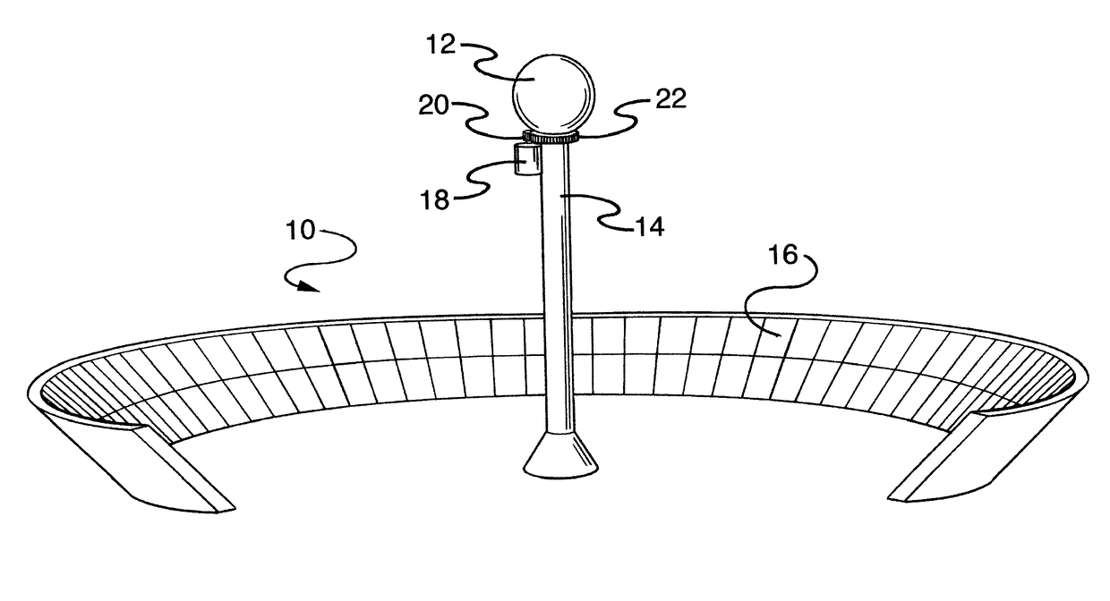
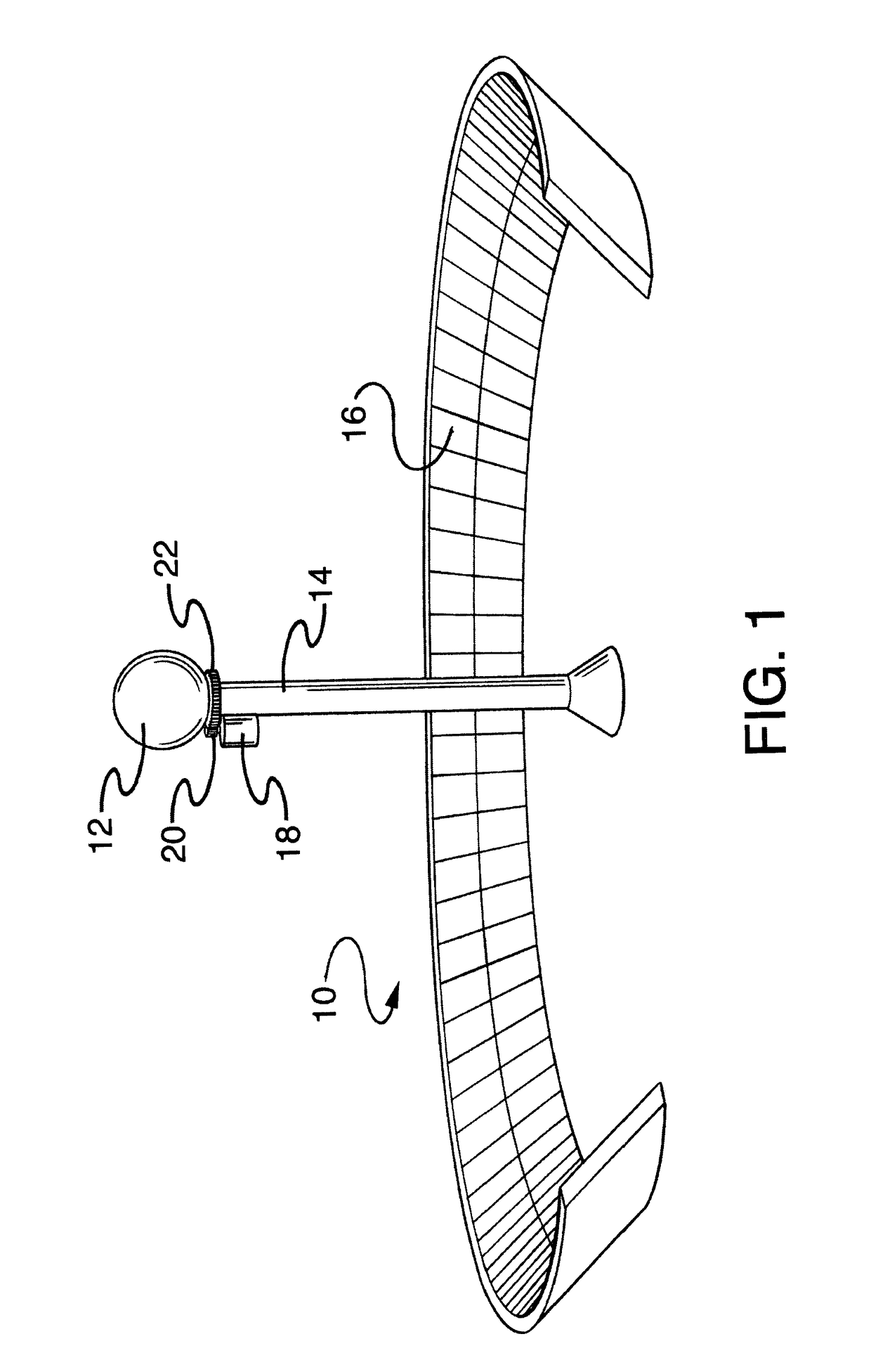
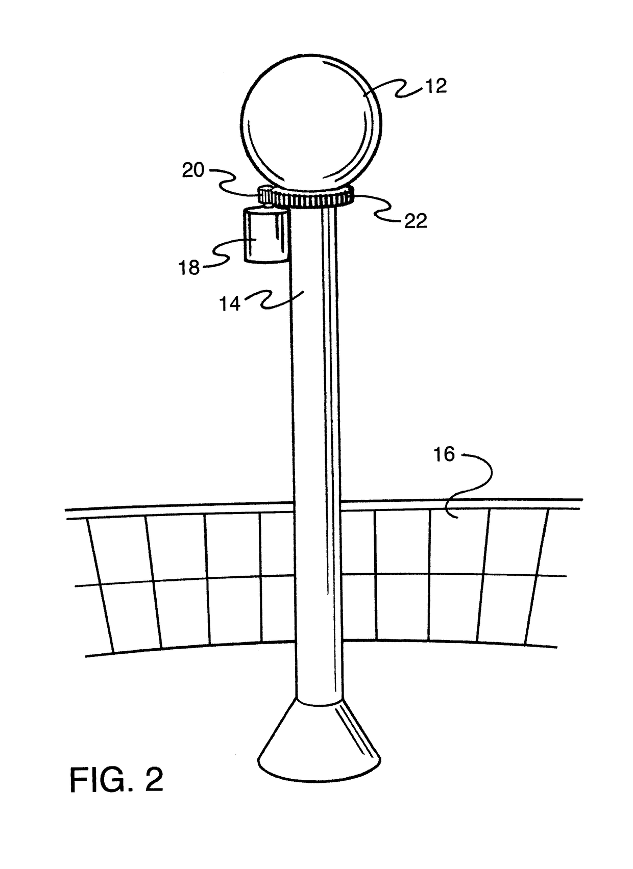
[0020]Referring now to the several drawings in detail wherein like reference numerals have been used throughout the various figures to designate like elements, there is shown in FIGS. 1 and 2 a solar power tower steam generating system constructed in accordance with the principles of the present invention and designated generally as 10. The solar power tower steam generating steam or solar power plant 10 is comprised essentially of a receiver 12 mounted for rotation adjacent the top of a tower 14. A plurality of heliostats or reflectors, schematically shown at 16 and supported on the ground, surround the tower 14 and the receiver 12 and direct rays from the sun onto the receiver for heating the same. The heliostats 16 shown schematically in FIGS. 1 and 2 are commonly referred to as a stadium array. Examples of such stadium array arrangements can be found in U.S. Pat. No. 4,136,674 to Korr and U.S. Published Patent Application No. 2009 / 0065054 to Gonzalez. This is, however, by way of...


PUM


Abstract

A solar power plant for generating steam is comprised of a spherical shell, the interior of which is sealed from the outside atmosphere and which is mounted adjacent the top of a vertical tower. A plurality of heliostats surrounds the tower and the direct sunrays onto the sphere for heating the same sphere. A spray nozzle within the sphere directs water supplied to it from an external source onto the interior surface of the sphere to create steam. The steam is withdrawn and directed to a turbine or the like for generating electricity. A motor rotates the sphere about its vertical axis thereby regularly exposing a different portion of the sphere to the heliostats to prevent the sphere from melting.

Description

FIELD OF THE INVENTION[0001]The present invention relates generally to electrical power generation systems, and more particularly to systems and methods that generate electrical power from solar energy.BACKGROUND OF THE INVENTION[0002]With the rapid expansion of the world's population, coupled with the technological developments in large areas of the world, a dramatic increase in the demand for energy in all forms, including fuels and electricity for heating, lighting, transportation and manufacturing processes has been created. The construction of hydroelectric facilities and the development of fossil fuel resources have continued as it has for many years.[0003]It has become increasingly evident, however, that for a number of reasons these efforts are inadequate to keep pace with the demands of the growing population. Furthermore, fossil fuel resources are known to be limited and the use of fossil fuels are also known to have a negative impact on the environment. It is well known, ...

Claims


Application Information

Patent Timeline
Patent Type & Authority Patents(United States)
IPC IPC(8): F03G6/06F03G6/00F24S20/20
CPCF03G6/06F24J2/54F24J2/4621F24J2/04F24J2/5406F24J2/07F03G6/065F24J2/4623F24J2002/0405Y02E10/47Y02E10/41F24J2002/075F03G2006/008Y02E10/46F24S30/422F24S2020/23F24S30/40F24S20/20F24S40/50F24S2020/18F24S40/52F24S10/00Y02E10/44Y02E10/40F03G6/063
Inventor JOHNSON, JR., RAYMOND
Owner JOHNSON JR RAYMOND
Why Eureka
Try Eureka