
Antenna structure and electronic device including the same

a technology of electronic devices and antennas, applied in the direction of antennas, antenna details, telephone set constructions, etc., can solve the problems of deterioration of antenna radiation characteristics, and achieve the effect of reducing influen

Pending Publication Date: 2022-09-08
SAMSUNG ELECTRONICS CO LTD
View PDF0 Cites 1 Cited by
  • Summary
  • Abstract
  • Description
  • Claims
  • Application Information

AI Technical Summary

Benefits of technology

This patent describes a foldable electronic device that includes a hinge structure with an antenna structure to prevent signal degradation during use. The antenna structure is advantageous when the device is unfolded, as it provides a radiation area without interfering with other antennas, and when the device is folded, it provides radiation to two opposite sides, improving antenna performance. The inclusion of the antenna structure in the hinge structure also allows for enhanced mounting space within the device.

Problems solved by technology

In an antenna structure disposed on the rear surface of an electronic device, the antenna radiation characteristics may be deteriorated as the surrounding structures block or interfere with a portion of the antenna radiation path when the foldable electronic device folds or unfolds.

Method used


Image

  • Antenna structure and electronic device including the same
  • Antenna structure and electronic device including the same
  • Antenna structure and electronic device including the same

Examples


Embodiment Construction

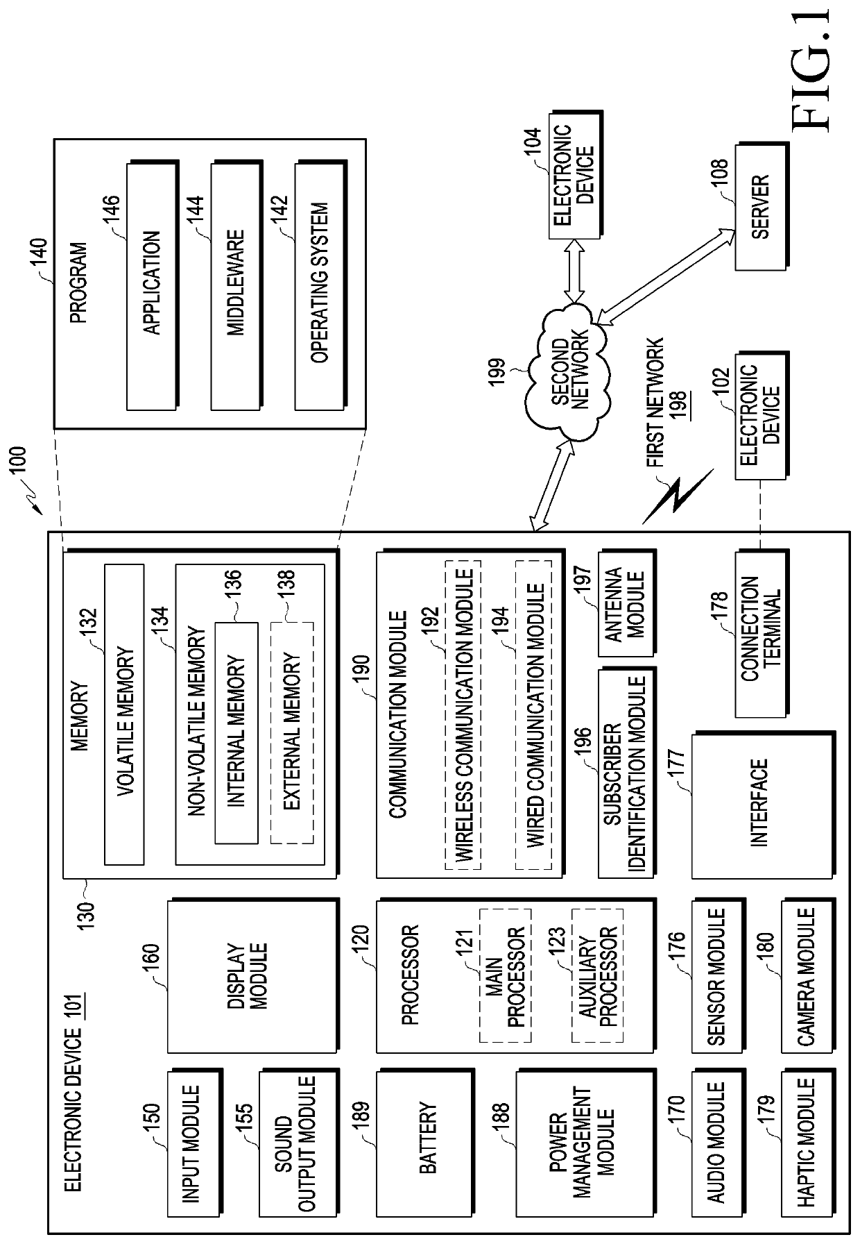
[0043]FIG. 1 is a block diagram illustrating an example electronic device in a network environment according to various embodiments of the disclosure.

[0044]Referring to FIG. 1, the electronic device 101 in the network environment 100 may communicate with an electronic device 102 via a first network 198 (e.g., a short-range wireless communication network), or an electronic device 104 or a server 108 via a second network 199 (e.g., a long-range wireless communication network). According to an embodiment, the electronic device 101 may communicate with the electronic device 104 via the server 108. According to an embodiment, the electronic device 101 may include a processor 120, memory 130, an input module 150, a sound output module 155, a display module 160, an audio module 170, a sensor module 176, an interface 177, a connecting terminal 178, a haptic module 179, a camera module 180, a power management module 188, a battery 189, a communication module 190, a subscriber identification ...


PUM


Abstract

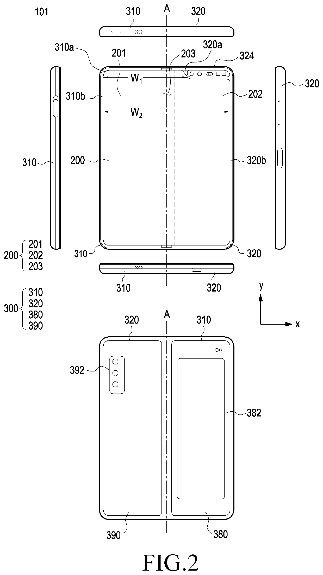
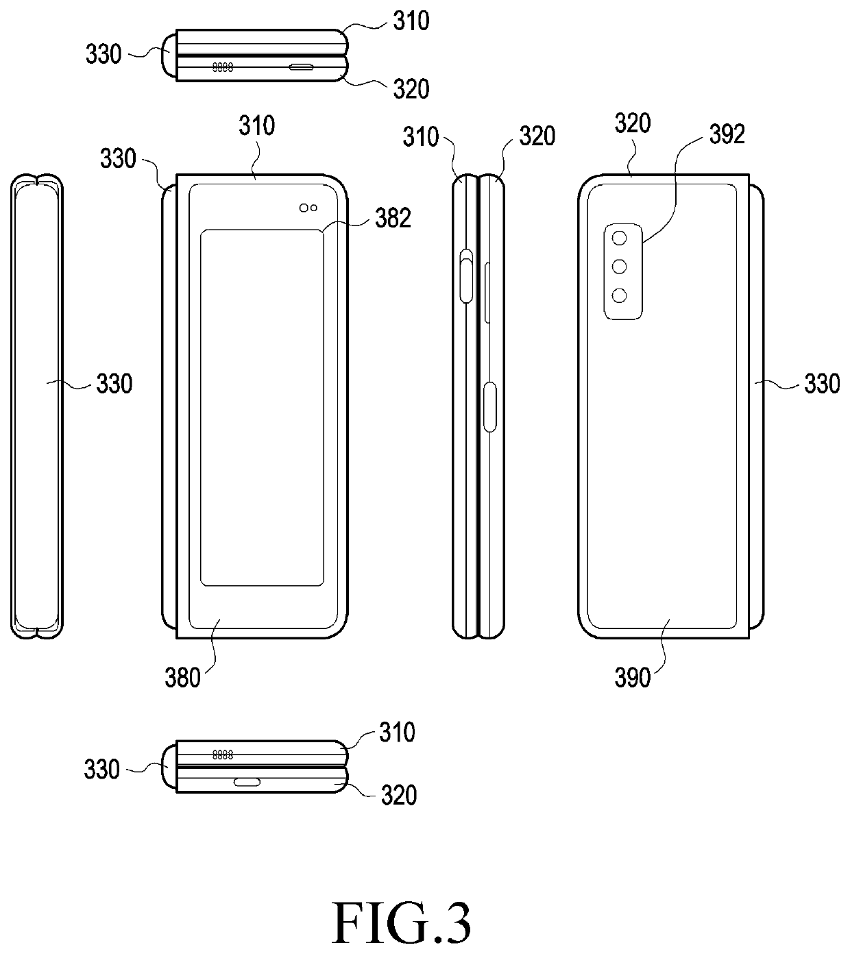
According to various embodiments of the disclosure, an electronic device may comprise: a first housing including a first insulating portion, a second housing including a second insulating portion adjacent to the first insulating portion, a hinge connecting the first housing and the second housing to be pivotable from a folded state to an unfolded state with respect to a pivot shaft, a hinge cover exposed to an outside and covering the hinge in the folded state and including a third insulating portion in at least a partial area thereof, a flexible display configured to be deformable in response to relative motion of the second housing with respect to the first housing, and an antenna structure including an antenna circuit board disposed in at least a partial area of the hinge and a plurality of antenna elements comprising at least one antenna forming an array on or in the antenna circuit board. In the unfolded state, the plurality of antenna elements may be disposed to overlap the first insulating portion and / or the second insulating portion, and in the folded state, the plurality of antenna elements may be disposed to overlap the third insulating portion of the hinge cover.

Description

CROSS-REFERENCE TO RELATED APPLICATIONS[0001]This application is a continuation of International Application No. PCT / KR2022 / 002295 designating the United States, filed on Feb. 16, 2022, in the Korean Intellectual Property Receiving Office and claiming priority to Korean Patent Application No. 10-2021-0028958, filed on Mar. 4, 2021, in the Korean Intellectual Property Office, the disclosures of which are incorporated by reference herein in their entireties.BACKGROUNDField[0002]The disclosure relates to an antenna structure and an electronic device including the antenna structure.Description of Related Art[0003]Advancing information communication and semiconductor technologies accelerate the spread and use of various electronic devices. In particular, recent electronic devices are being developed to carry out communication while carried on.[0004]The term “electronic device” may refer to a device performing a particular function according to its equipped program, such as a home applian...

Claims


Application Information

Patent Timeline
Patent Type & Authority Applications(United States)
IPC IPC(8): H04M1/02H01Q1/22H01Q1/24
CPCH04M1/0218H04M1/0268H01Q1/2283H01Q1/243H01Q21/28H04M1/0216H04M1/026
Inventor SEO, SEUNGHANSONG, JAEHOONSON, DONGIL
Owner SAMSUNG ELECTRONICS CO LTD
Learn More