Imaging systems and methods

a fluoroscopic image and imaging system technology, applied in the field of improved methods and systems for xray and fluoroscopic image capture, can solve the problems of increasing the cost of existing fluoroscopic machines, and increasing the cost of existing machines

Pending Publication Date: 2022-09-15
OXOS MEDICAL INC
View PDF10 Cites 3 Cited by
  • Summary
  • Abstract
  • Description
  • Claims
  • Application Information

AI Technical Summary

Benefits of technology

[0018]The invention relates to an improved versatile, multimode radiographic systems and methods, allowing the surgeon to operate on a patient without interference, and capture static and dynamic x-rays and other still and video imagery without repositioning equipment, the subject or the surgeon.
[0019]Both x-ray emitters and detectors are described. One variation of a novel emitter allows for portable control of the emitter. Such an emitter can be lightweight and extremely maneuverable. Variations include that the portable emitter that is a handheld unit. Alternatively, the portable emitter can be affixed to a mounting structure that is either automated / controllable or simply bears the weight of the emitter to prevent the user from constantly holding the emitter. In additional variations, the emitter can be designed so that it is releasably coupleable with a mounting structure, which allows improved portability when needed and coupling to a mounting structure when desired. The emitter may include both an x-ray emitter along with at least one additional imaging modality such as a digital camera for producing a visual image, a thermal image, and an infrared image of a patient for the purposes of aiding diagnostic, surgical, and non-surgical interventions. Clearly, the systems and methods described herein can be used for non-medical applications where non-invasive imaging is desirable.
[0020]Ergonomic controls make acquisition of images easier and faster and a built-in display facilitates easy-to-use control functions. The device senses its distance from the subject and will block the activation and discharge of radiation if the x-ray tube is not at a safe distance; i.e., too close to the patient. The minimum distance can be defined in software and is adjustable based on intended use and other factors. The system automatically and intelligently manages its power state through the implementation and use of an inertial measurement unit (IMU) and various timing components.
[0021]The x-ray emitter may be used with any available x-ray detector. One option is to mount the emitter in a fixture including a properly aligned detector plate, much like a traditional c-arm, though much smaller and more capable. An alternate variation is described herein and includes use of an emitter with a distinct x-ray capture stage, disclosed in detail, which automatically pivots, orients and aligns itself with the emitter to maximize exposure, quality and safety.
[0029]In use, the stage precisely tracks the position and angle of the x-ray emission, positioning and tilting the embedded sensor exactly to capture a precise, high quality x-ray image. The stage uses less power, corrects for any skew or perspective in the emission, allows the subject to remain in place, and allows the surgeon's workflow to continue uninterrupted.

Problems solved by technology

Current fluoroscopic machines for orthopedic surgery tether a radiation source to an image intensifier by way of a large, fixed ‘c-arm.’ Manipulation of these larger, less portable machines is difficult and time consuming.
It is frequently necessary to reposition the subject to fit the attainable field of view, which can be problematic during sensitive stages of a procedure.
Thus, while c-arms are ergonomically suitable for surgical treatment of the spine and larger joints, existing units are heavy and cumbersome with respect to hand / wrist / arm and foot / ankle / leg extremity surgery, where relevant anatomy is smaller and more moveable by the surgeon.
Existing fluoroscopic machines are also expensive and emit large doses of radiation.
In many cases, these larger radiation doses are not required for more delicate procedures, on extremities, for example, unnecessarily exposing the patient and surgeon to these higher doses.
However, because existing fluoroscopic machines only capture x-ray images, the need to switch between digital and / or thermal image capture devices may create a delay in the completion of the surgery.
Further, in a number of situations, the digital or thermal camera is not a sterile device, forcing the surgeon to either violate the surgical field, take a picture and then scrub back in, or have an assistant take the picture, which can create confusion about image correlation.
From a collimation standpoint, this creates a new set of challenges that are not addressed by traditional collimator designs.
Setting these technique factors can be complex.
This approach has a number of problems.
The major issue with the existing approach is movement.
Because the radiation is exposing the subject for an extended time period, any movement whatsoever, either in the subject, the operator, the machine, vascularity inside the subject, etc., will create motion artifacts that severely degrade the image.
Also, in traditional systems, penetration requirements are not known before the exposure; therefore, as the source emits radiation at a given power level (kV), frequently there is not be enough penetration to render an image.
This failure to render an image exposes the patient, operator and staff to excess radiation without any clinical purpose.

Method used


Image

  • Imaging systems and methods
  • Imaging systems and methods
  • Imaging systems and methods

Examples


Embodiment Construction

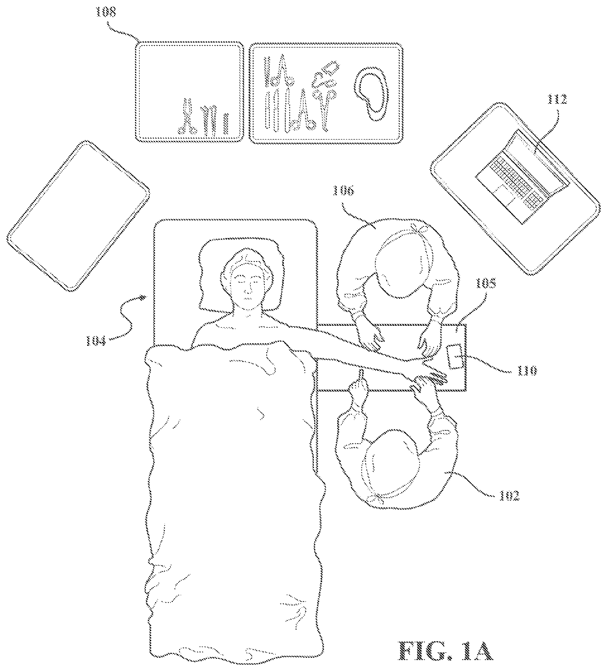
[0110]FIG. 1A depicts an example of operating room layout for use of an imaging system in a standard surgery of an extremity case. In this example, the surgeon 102 is operating on the patient's left hand. The patient 104 is lying in the supine position with the left upper extremity prepped and draped on a hand table 105 in the abducted position. The surgeon sits adjacent to the patient's side while a surgical assistant 106 sits across the hand table adjacent to the patient's head. Surgical instruments and equipment are laid out on the back table 108 immediately behind the surgical assistant.

[0111]In one variation, the imaging system uses x-ray imaging. As such, a sterilized x-ray emitter 110 according to the invention is placed on the surgical hand table 105 for use. A monitor 112 is positioned on a stand immediately adjacent to the hand table whereby x-ray, fluoroscopic, thermal and digital images can be wirelessly transferred from the x-ray imaging system to the screen for surgeon...


PUM


Abstract

Methods and systems for x-ray and fluoroscopic image capture and, in particular, to a versatile, multimode imaging system incorporating a hand-held x-ray emitter operative to capture digital or thermal images of a target; a stage operative to capture static x-ray and dynamic fluoroscopic images of the target; a system for the tracking and positioning of the x-ray emission; a device to automatically limit the field of the x-ray emission; and methods of use. Automatic systems to determine the correct technique factors for fluoroscopic and radiographic capture, ex-ante.

Description

REFERENCE TO RELATED APPLICATIONS[0001]This application is a continuation of U.S. patent application Ser. No. 17 / 163,878 filed Feb. 1, 2021, which is a continuation of PCT Application No. PCT / US2019 / 044727 filed Aug. 1, 2019, which claims priority to U.S. Provisional Applications 62 / 712,981 filed Aug. 1, 2018 and 62 / 817,561 filed Mar. 13, 2019, the entireties of all applications are incorporated by reference herein.FIELD OF THE INVENTION[0002]This invention relates generally to improved methods and systems for x-ray and fluoroscopic image capture and, in particular, to a versatile, multimode imaging system incorporating a hand-held x-ray emitter operative to capture digital or thermal images of a target; a stage operative to capture static x-ray and dynamic fluoroscopic images of the target; a system for the tracking and positioning of the x-ray emission; a device to automatically limit the field of the x-ray emission; and methods of use. The invention also includes an automatic sys...

Claims


Application Information

Patent Timeline
Patent Type & Authority Applications(United States)
IPC IPC(8): A61B6/00
CPCA61B6/547A61B6/4417A61B6/4452A61B6/487A61B6/587A61B2560/0487A61B2562/0233A61B6/06H04N5/321G01N23/04G21K4/00G01N23/223A61B6/4405A61B6/08
Inventor RUFF, EVANBENNETT, PAULVISHWAKARMA, DHRUVKOLOVICH, GREGORY
Owner OXOS MEDICAL INC
Why Eureka
Try Eureka