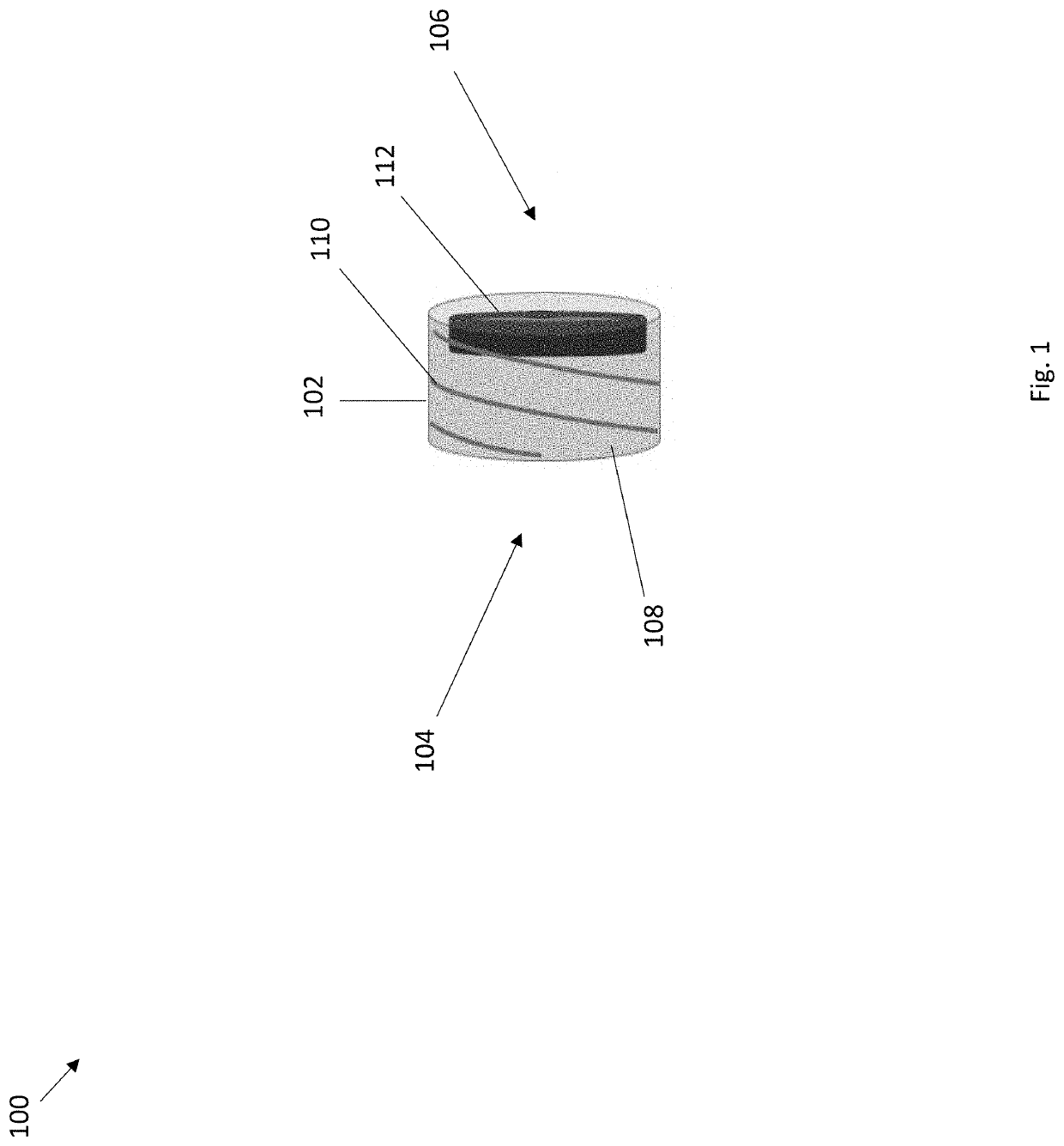
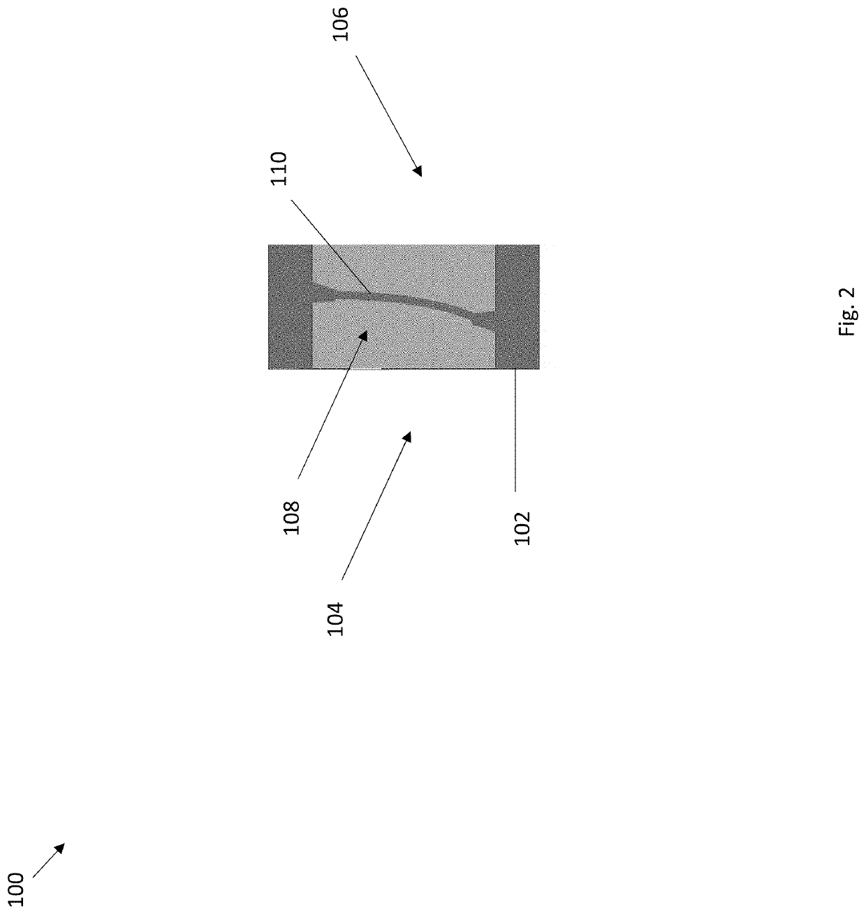
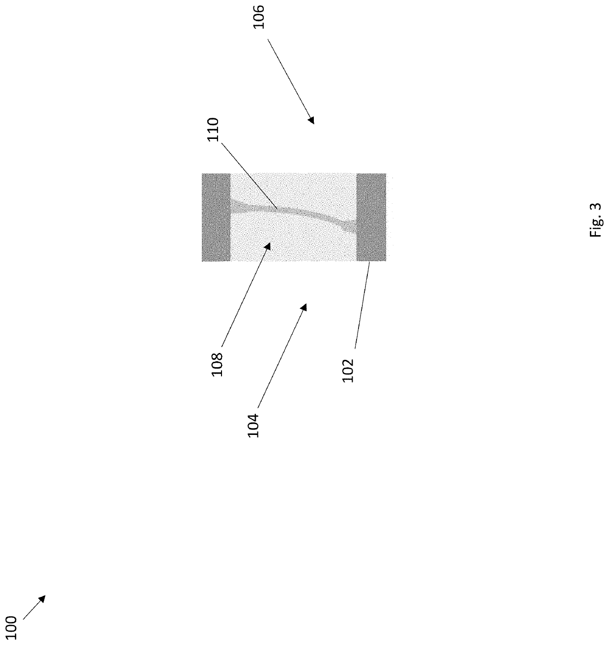
Lamprey lock device
a technology of locking device and lamprey, which is applied in the direction of catheters, valves, other medical devices, etc., can solve the problem of limited flow rate at connections
- Summary
- Abstract
- Description
- Claims
- Application Information
AI Technical Summary
Benefits of technology
Problems solved by technology
Method used
Image
Examples
experimental examples
[0106]The invention is further described in detail by reference to the following experimental examples. These examples are provided for purposes of illustration only and are not intended to be limiting unless otherwise specified. Thus, the invention should in no way be construed as being limited to the following examples, but rather, should be construed to encompass any and all variations which become evident as a result of the teaching provided herein.
[0107]Without further description, it is believed that one of ordinary skill in the art may, using the preceding description and the following illustrative examples, make and utilize the compounds of the present invention and practice the claimed methods. The following working examples therefore specifically point out exemplary embodiments of the present invention and are not to be construed as limiting in any way the remainder of the disclosure.
example 1
ock Flow Data
Experimental Setup
[0108]In vitro experiments simulated drainage of serous / purulent fluid (FIG. 36). In this experimental setup a 14 French drainage catheter (Total Abscession; Angiodynaics; Queensbury, N.Y.) was inserted into a compressible reservoir. The distal female end of the drainage catheter was then connected to either a Luer connector or Lamprey lock. The reservoir was filled to an initial volume of 500 mL and was elevated above the catheter outlet to a constant fluid column height of 20 cm. Gravity drainage occurred into an open beaker atop an electronic balance (Precision Balances Model ML802T / 00; Mettler-Toledo, Greifensee, Switzerland). Mass and time were simultaneously recorded at fixed intervals for a specified duration to determine mean drainage rate, total drainage time, and cumulative drainage or percentage of total volume drained. To calculate drainage rate, units of mass were converted to volume by dividing mass by specific gravity. Each experimental ...
PUM
 Abstract
Description
Claims
Application Information
 - R&D
- Intellectual Property
- Life Sciences
- Materials
- Tech Scout
- Unparalleled Data Quality
- Higher Quality Content
- 60% Fewer Hallucinations
Browse by: Latest US Patents, China's latest patents, Technical Efficacy Thesaurus, Application Domain, Technology Topic, Popular Technical Reports.
© 2025 PatSnap. All rights reserved.Legal|Privacy policy|Modern Slavery Act Transparency Statement|Sitemap|About US| Contact US: help@patsnap.com


