
Methods and Systems for Analyzing and Predicting Aeroelastic Flutter on Configurable Aircraft

a technology of aeroelastic flutter and configurable aircraft, which is applied in the direction of aircraft components testing, geometric cad, design optimisation/simulation, etc., can solve the problems of many types of engineered structures, such as skyscrapers, bridges, aircraft airframes, and unstable oscillatory aeroelastic deformation, and it is impractical to conduct such testing for different aircra

Pending Publication Date: 2022-09-22
View PDF0 Cites 0 Cited by
  • Summary
  • Abstract
  • Description
  • Claims
  • Application Information

AI Technical Summary

Benefits of technology

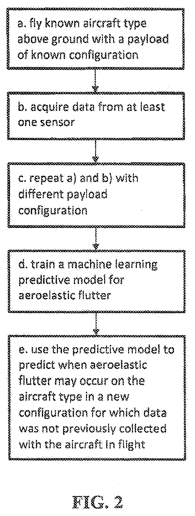
This patent describes a method and system for analyzing and predicting aeroelastic flutter on an aircraft. The method involves observing data from sensors on the aircraft while it flies above ground, and then training a machine learning predictive model using the data collected. The predictive model can then be used to predict when aeroelastic flutter may occur on the aircraft in a new configuration for which data from sensors was not previously collected. The system includes the predictive model and a warning mechanism that alerts the pilot of an impending flutter condition. The technical effect of this patent is to enable early detection and timely warning of aeroelastic flutter on an aircraft, which can help prevent damage and improve safety.

Problems solved by technology

Many types of engineered structures, such as skyscrapers, bridges, and aircraft airframes, are subject to vibrational stresses which can be caused by aerodynamic forces due to wind, for example, or due to the airspeed of an aircraft in flight.
The aerodynamic forces over such structures may cause an unstable oscillatory aeroelastic deformation, or vibration, of the structure referred to as flutter.
However, it is very impractical to conduct such testing for different aircraft, each having many possible configurations.
In addition, the initiation of flutter in an aircraft's wings may cause damage to the wings.
It has been found that finite element analysis produces results that are not always sufficiently accurate.

Method used


Image

  • Methods and Systems for Analyzing and Predicting Aeroelastic Flutter on Configurable Aircraft
  • Methods and Systems for Analyzing and Predicting Aeroelastic Flutter on Configurable Aircraft

Examples


Embodiment Construction

[0025]The present invention relates generally to methods and systems for analyzing and predicting aeroelastic flutter on aircraft and, more particularly, to methods and systems for analyzing and predicting aeroelastic flutter on configurable aircraft that are able to warn a stakeholder of the conditions that may cause aeroelastic flutter.

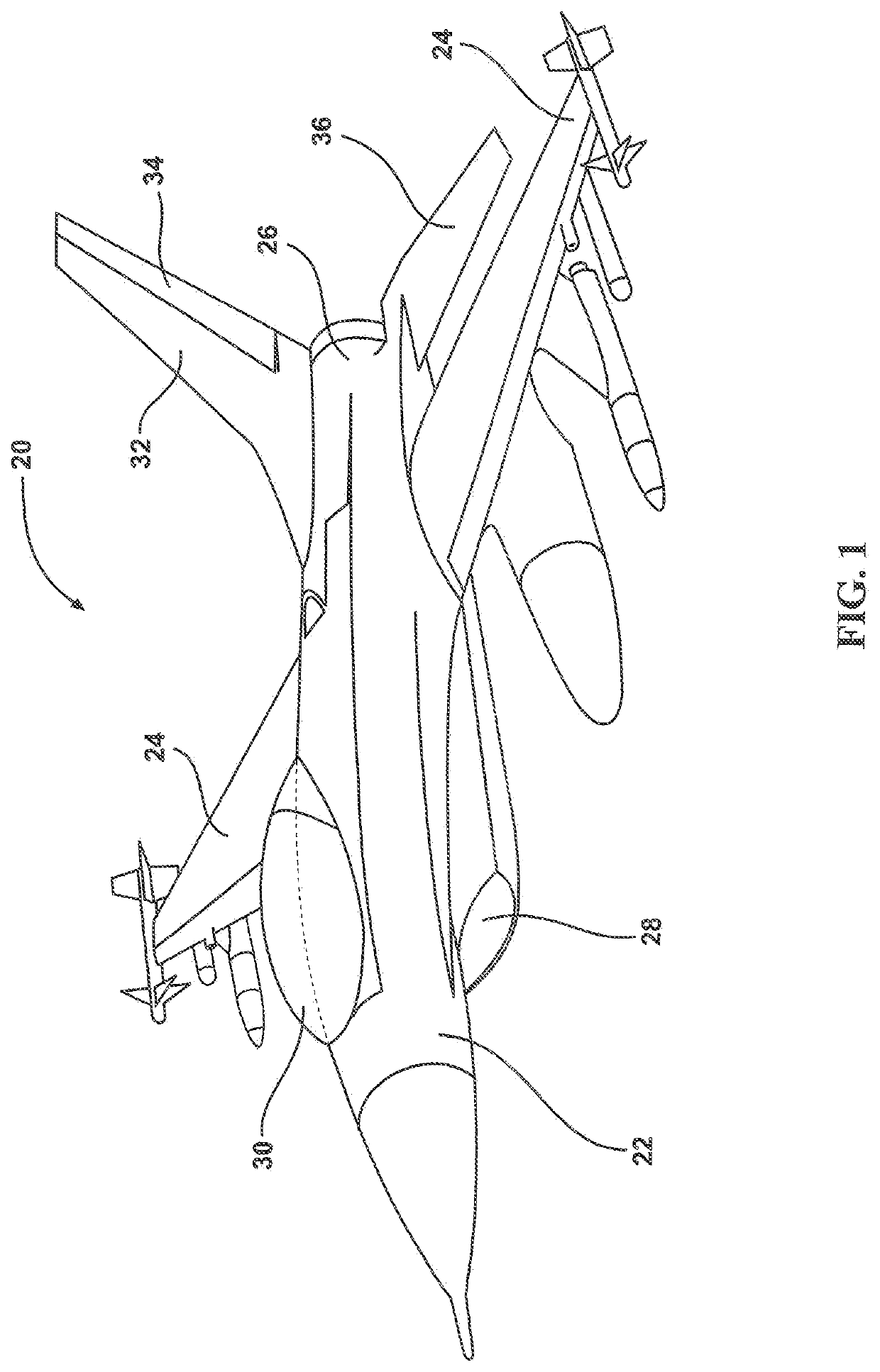
[0026]The term “aircraft” refers to a machine that can fly. For the purposes of the present invention, the term aircraft refers to a flying machine that may experience aeroelastic flutter. There are perhaps thousands of aircraft types, which may include but are not limited to: BAC (Jet Provost, Strikemaster, TSR-2), Boeing YB-9, General Dynamics F-16 Fighting Falcon, Lockheed Martin F22 Raptor, Lockheed Martin F-35 Lightning II, Lockheed XFV, McDonnell Douglas F-15 E Strike Eagle, and Northrop F-5, to name a few.

[0027]To distinguish the many airplanes produced of the same type, a tail number may be assigned. For example, General Dynamics may have pr...


PUM


Abstract

Methods and systems for analyzing and predicting aeroelastic flutter on configurable aircraft are disclosed herein. The method may include the steps of: a) flying a known aircraft type above ground, wherein the aircraft has a payload in a known configuration; b) acquiring data from at least one sensor on the aircraft while flying above ground; c) repeating steps a) and b) with a different payload configuration; d) training a machine learning predictive model for the aircraft type for aeroelastic flutter using the collected data; and e) using the predictive model to predict when aeroelastic flutter may occur on the aircraft type when the aircraft has a payload in a new configuration for which data from sensors was not previously collected with the aircraft in flight.

Description

[0001]Pursuant to 37 C.F.R. § 1.78(a)(4), this application claims the benefit of and priority to prior filed co-pending Provisional Application Ser. No. 63 / 163,074 filed Mar. 19, 2021, which is expressly incorporated herein by reference.RIGHTS OF THE GOVERNMENT[0002]The invention described herein may be manufactured and used by or for the Government of the United States for all governmental purposes without the payment of any royalty.FIELD OF THE INVENTION[0003]The present invention relates generally to methods and systems for analyzing and predicting aeroelastic flutter on aircraft and, more particularly, to methods and systems for analyzing and predicting aeroelastic flutter on configurable aircraft that are able to warn a stakeholder of the conditions that may cause aeroelastic flutter.BACKGROUND OF THE INVENTION[0004]Many types of engineered structures, such as skyscrapers, bridges, and aircraft airframes, are subject to vibrational stresses which can be caused by aerodynamic fo...

Claims


Application Information

Patent Timeline
Patent Type & Authority Applications(United States)
IPC IPC(8): G06F30/15G06F30/27B64F5/60
CPCG06F30/15G06F30/27B64F5/60
Inventor BAKER, BRANDON
Learn More