Unlock instant, AI-driven research and patent intelligence for your innovation.

Operation method of proximity sensor

Pending Publication Date: 2022-09-29
SENSORTEK TECH
View PDF0 Cites 0 Cited by
  • Summary
  • Abstract
  • Description
  • Claims
  • Application Information

AI Technical Summary

Benefits of technology

The patent text describes an operation method for a proximity sensor that can effectively and easily reduce ambient light levels and achieve better sensing results. This is achieved by adjusting the timing of the light-source turn-on and off operations to cancel out the ambient-light components.

Problems solved by technology

Unfortunately, the sensing result of the optical sensor 103 includes the component of ambient light.
If the sensing time interval between the light-source under turn-on ON state and the light-source under turn-off OFF state is too long, the difference between two sensed luminance values will be too large so that the component of the ambient light A may not be subtracted by the proximity sensor 100, and thus a larger sensing error is generated.
Thereby, if the processing circuit 107 subtracts the integration over the light-source turn-off operation p2 from the integration over the light-source turn-on operation p1, the component of the ambient light A may not be subtracted completely and thus contribute a substantial noise signal in the sensing result.
Although the mentioned method for shortening the operation period of light-source turning on and turning off may reduce the remaining ambient-light component in the sensing result actually, the operation frequency of the circuit is limited by the operation speed of devices.
It is not possible to increase the operation frequency unlimitedly for shortening the operation period of light-source turning on and turning off.

Method used


Image

  • Operation method of proximity sensor
  • Operation method of proximity sensor
  • Operation method of proximity sensor

Examples


Embodiment Construction

[0018]In order to make the structure and characteristics as well as the effectiveness of the present application to be further understood and recognized, the detailed description of the present application is provided as follows along with embodiments and accompanying figures.

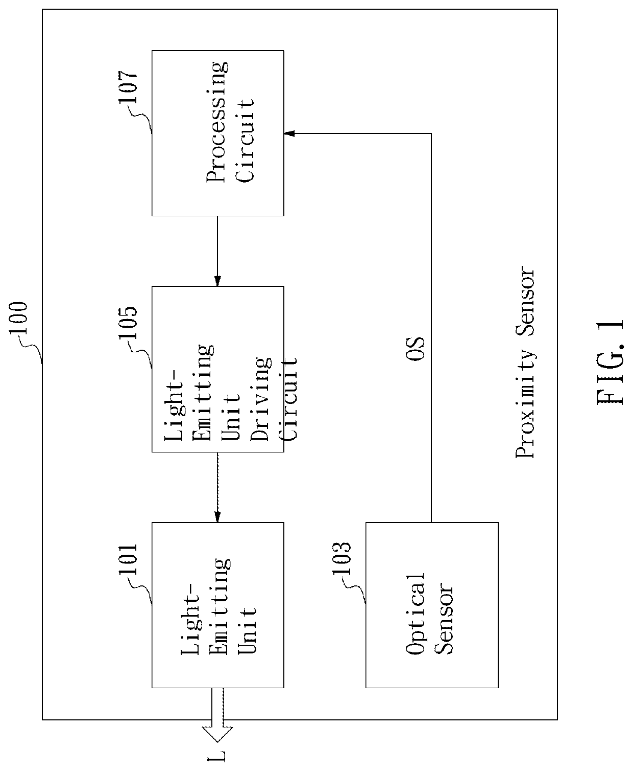
[0019]First, please refer to FIG. 3, which shows a flowchart of the control method of proximity sensor according to an embodiment of the present application. The control method of proximity sensor according to the present application may be applied to controlling the structure of the proximity sensor 100 as shown in FIG. 1.

[0020]The operation method of proximity sensor according to the present application comprises steps of:

[0021]A processing circuit 107 controls a light-emitting unit driving circuit 105 so that the light-emitting unit driving circuit 105 supplies a driving current to a light-emitting unit 101 and further the light-emitting unit 101 is driven by the driving current to emit light L. The emitted ...


PUM


Abstract

An operation method of a proximity sensor comprises: controlling a light-emitting element by a processing circuit. Such control includes a plurality of light source on and light source off operations. An optical sensor receives light and outputs a sensing signal corresponding to the intensity of the light. The processing circuit computes the sensing signal to produce a sensing result. The plurality of light source on and light source off operations includes a group having two light sources on operations and two light sources off operations. The two light sources on operations in the group or the two light sources off operations in the group are performed consecutively. In this way, the ambient light components of the light source on and off operations may cancel out each other to reduce the ambient light components contained in the sensing results.

Description

FIELD OF THE INVENTION[0001]The present application generally relates to a control method of a proximity sensor, and particularly to an operation method of the proximity sensor.BACKGROUND OF THE INVENTION[0002]Proximity sensors are widely applied to portable electronic devices such as mobile phones or tablet computers that everyone owns. A regular application is that during a call, a smartphone will detect the distance between the user and the panel using a proximity sensor so that the control unit inside the smartphone may judge whether to turn off the touch or display functions of the panel according to the sensing result of the proximity sensor.[0003]As shown in FIG. 1, in a proximity sensor 100 according to the prior art, a light-emitting unit 101 (for example, a light-emitting diode LED, a laser diode LD) generates light L. The light L is reflected by a reflector (for example, a human body or reflective objects) and generates corresponding reflection light. The reflection light...

Claims


Application Information

Patent Timeline
IPC IPC(8): H05B47/11H05B47/155H05B47/165H05B47/17
CPCH05B47/11H05B47/155H05B47/165H05B47/17H04M1/72454H04M1/22H04M2250/12G01S17/04H03K17/945G01S7/487G01S7/484H03K2217/941H03K2217/94116
Inventor LIN, MENG-YONGLIU, MING-HUANGHSU, JER-HAULIU, CHENG-FENG
Owner SENSORTEK TECH