

Glove structure and its manufacaturing method
a technology of glove structure and manufacuring method, which is applied in the field of functional construction of glove structure, can solve the problems of user's hands being uncomfortable and muggy, the breathability of non-injection molding assembly will be dead or even lost, and the weight and thickness of the glove are thus increased
- Summary
- Abstract
- Description
- Claims
- Application Information
AI Technical Summary
Benefits of technology
Problems solved by technology
Method used
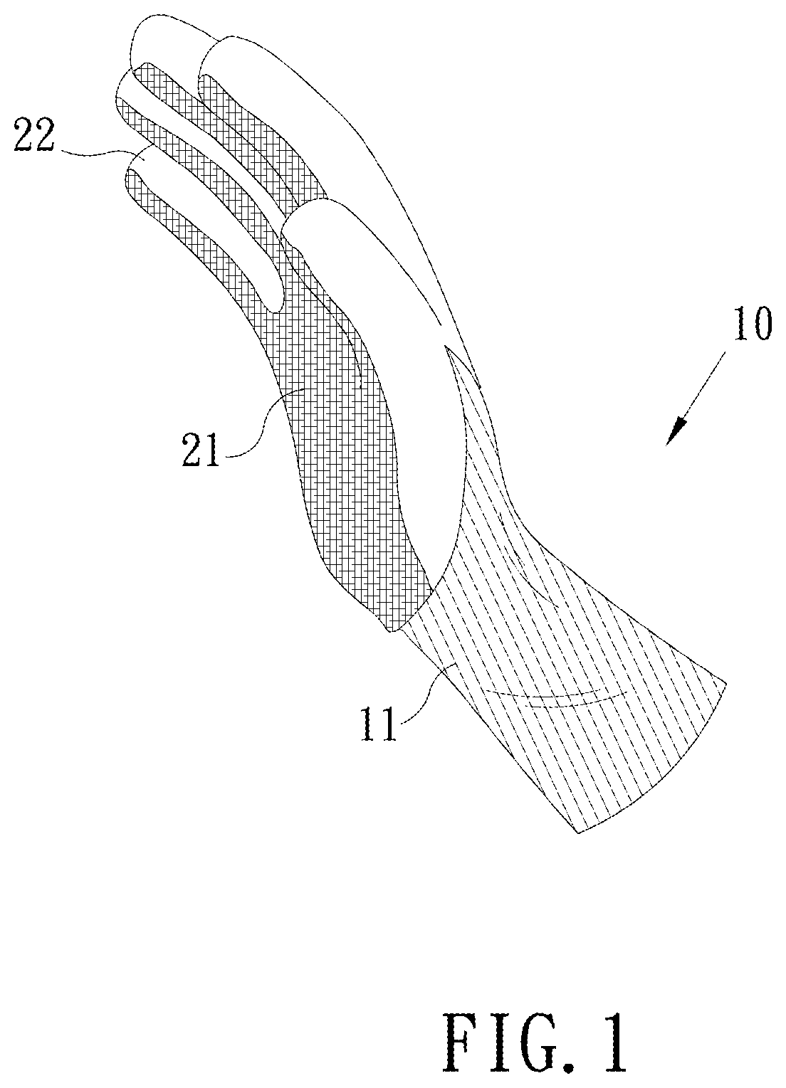
Image

Examples
sixth embodiment
[0090]Refer to FIG. 9 and FIG. 11, and FIG. 11 is a perspective three-dimensional view of a partial of a glove structure according to the present disclosure. The piece 21 can be designed to be provided with at least one interior via H2 which is located in the inside portion away from the section S3 and penetrates the piece 21. Being different from the edge via H1 which is located in the section S3, there is a distance between the interior via H2 and the section S3, and the distance is preferably larger than 1 millimeter. The injection molding assembly 22 can fully fill the interior via H2, so as to increase the bonding force between the injection molding assembly 22 and the section S3. Another design may consider the tradeoff between the breathability, the comfort and the bonding force, and the injection molding assembly 22 partially fills the interior via H2. In addition, the injection molding assembly 22 may not fill the interior via H2, so as to increase the softness and breathab...
seventh embodiment
[0091]Next, refer to FIG. 12, and FIG. 12 is a three-dimensional view of a glove structure according to the present disclosure. In the embodiment, the least an interior via H2 is a plurality of interior vias H2, and the interior vias H2 are arranged in a longitude direction and a latitude direction of a palm surface. The longitude direction and the latitude direction of the palm surface correspond to a part of the palm joints. By arranging the interior vias H2 in the longitude direction and the latitude direction of the palm surface, it is more breathable and more comfortable to the hand of the user when the user wears the glove structure 10 to operate. In other embodiment, the interior vias H2 may be arranged in the longitude direction or the latitude direction of the palm surface. Further, according the actual requirements, the edge via H1 may be not provided, but only the interior vias H2 are provided.
[0092]Still refer to FIG. 12. In FIG. 12, the piece 21 covers a palm surface of...
eighth embodiment
[0095]Refer to FIG. 14, and FIG. 14 is a section view of a partial structure of a glove structure according to the present disclosure. In the embodiment of the present disclosure, the bonding layer 23 enters at least a part of inside of the piece 21 via the bottom surface S2 of the piece 21. Specifically, at least a part of the bonding layer 23 penetrates at least a part of the piece 21 and partial interior vias H2, and / or the bonding the layer 23 enters at least a part of inside of the glove core 11 via the outer surface S1 of the glove core 11. After testing, this approach has produced an unexpected effect, and the wear resistance of the glove structure 10 is increased by about 50%.
[0096]Moreover, the bonding layer 23 can be an extra bonding layer or formed by at least one of the piece 21 and the glove core 21. Refer to FIG. 15A to FIG. 15C, FIG. 15A is a section view of a partial structure of a glove structure according to the ninth embodiment of the present disclosure, FIG. 15B ...
PUM
| Property | Measurement | Unit |
|---|---|---|
| distance | aaaaa | aaaaa |
| angle | aaaaa | aaaaa |
| perimeter | aaaaa | aaaaa |
Abstract
Description
Claims
Application Information