Rotating apparatus for a tool part of a shaping machine

a technology of rotating apparatus and shaping machine, which is applied in the direction of presses, manufacturing tools, etc., can solve the problems of high cost and potential leakage of media

Pending Publication Date: 2022-10-06
ENGEL AUSTRIA
View PDF2 Cites 0 Cited by
  • Summary
  • Abstract
  • Description
  • Claims
  • Application Information

AI Technical Summary

Benefits of technology

[0009]The object of the invention is to provide a rotating apparatus of the general kind set forth, in which the problems discussed in relation to the state of the art are avoided and to provide a closing unit for a shaping machine having at least one such rotating apparatus and a shaping machine having such a closing unit.
[0016]Preferably, lines which are in the form of hoses of the first media routing extend persistently starting from the first rotor part to a connecting location on the rotary plate (preferably in the form of hoses which are in one piece over the entire length, less preferably in the form of interconnected portions), which permits simple dismantling.
[0018]The direct hose communication and / or pipe communication of the first mediarouting from the first rotor part to the rotary plate affords some advantages:
[0042]The connecting part can have at least one passive cooling device, preferably bores and / or slots. If a central opening is provided in the connecting part, a passive cooling device in the form of openings in the connecting part, that extend to the central opening and which are arranged at the casing of the connecting part, permits air exchange in respect of the central opening with the environment (in the manner of a chimney effect) and thus reduces a temperature loading in respect of the second media routing.

Problems solved by technology

A problem here is that this structure requires a large number of bored shafts which are arranged in a row with each other, with interfaces and sealing elements.
It is therefore highly cost-intensive and potentially susceptible to leakage of the media.

Method used


Image

  • Rotating apparatus for a tool part of a shaping machine
  • Rotating apparatus for a tool part of a shaping machine
  • Rotating apparatus for a tool part of a shaping machine

Examples


Embodiment Construction

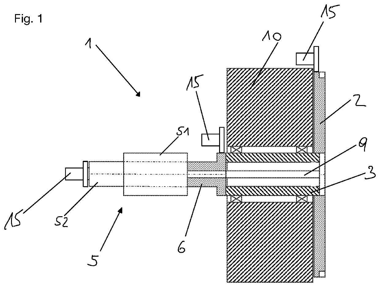
[0063]FIG. 1 shows a rotating apparatus 1 for a tool part of a shaping machine comprising a rotary plate 2 for mounting a tool part (not shown) and a rotary shaft 3 connected to the rotary plate 2. The rotary shaft 3 is mounted by way of rotary bearings in a passage opening of a mold mounting plate (the mold mounting plate is here mounted moveably on a machine bed that is not shown).

[0064]A stator 4 of the rotary feedthrough (together with the connections leading to the stator 4) and a linear drive for performing a linear movement in order to lift the rotary plate 2 (which here is in the form an index plate) off the mold mounting plate 10 are not shown and correspond to the state of the art. By way of example three different options are shown in respect of positions of a rotary drive 19.

[0065]This embodiment has a rotary feedthrough for an endless rotation comprising a rotor 5 connected to the rotary shaft 3 for feeding through at least two different media to the rotary plate 2, whe...


PUM

PropertyMeasurementUnit
temperatureaaaaaaaaaa
shapeaaaaaaaaaa
thermal insulatingaaaaaaaaaa

Abstract

A rotating apparatus includes a rotary plate for mounting a tool part, a rotary shaft connected to the rotary plate, a rotary feedthrough including a stator, and a rotor connected to the rotary shaft for feeding through at least two media to the rotary plate. The rotor has a first rotor part for feeding through a first medium and a second rotor part for feeding through a second medium, and the first and the second rotor parts are thermally separated from each other. A first media routing for the first medium is in the form of a hose and / or pipe for the first medium from the first rotor part past the connecting part to the rotary plate. A connecting part is non-rotatably connected to the second rotor part and the rotary shaft. The hose and / or pipe extends from the first rotor part.

Description

BACKGROUND OF THE INVENTION[0001]The present invention concerns a rotating apparatus for a tool part of a shaping machine, a closing unit for a shaping machine having at least one such rotating apparatus and a shaping machine having such a closing unit.[0002]Rotating apparatuses for a tool part of a shaping machine are known both for rotary plates having a vertical axis of rotation and also for rotary plates having a horizontal axis of rotation. The tool part (which itself can be of a multi-part configuration) together with at least one further tool part forms a cavity for shaping a shaped part. If there is no possibility of a linear movement of the rotary plate, then the rotary plate is usually referred to as a turntable, while if a linear movement is involved, then reference is made to an index plate.[0003]A rotating apparatus having an index plate is shown in DE 10 2019 107 720 A1.[0004]In order to feed media to the rotary plate or to a tool part arranged on the rotary plate or t...

Claims


Application Information

Patent Timeline
Patent Type & Authority Applications(United States)
IPC IPC(8): B29C45/04
CPCB29C45/045B29C45/162B29C45/2681B29C33/0083B29C45/7312B29C45/0441B29C45/64B29C45/72B30B15/02B30B15/34B22D17/20B22D17/00B29C45/06B29C45/04
Inventor POROD, FLORIAN
Owner ENGEL AUSTRIA
Why Eureka
Try Eureka