A helical strake set to reduce vortex induce vibrations of an eolic tower

a technology of eolic tower and helical strake, which is applied in the direction of wind motor supports/mounts, machines/engines, engine fuctions, etc., can solve the problems not only onshore, but also in the assembly of large wind turbine towers, and achieve the effect of reducing the vibration of the vortex

Pending Publication Date: 2022-10-06
GAMESA INNOVATION & TECH SA
View PDF6 Cites 0 Cited by
  • Summary
  • Abstract
  • Description
  • Claims
  • Application Information

AI Technical Summary

Benefits of technology

[0036]FIG. 6b shows the helical strake set arrange in streamline around the cross section of the tower outer surface to reduce vortex induce vibrations.

Problems solved by technology

The assembly of large wind turbine towers in particular under offshore conditions, but also onshore, consumes a lot of time, effort, and financial resources.
Thereby, lifting the tower in segments or as a whole to the assembly site, i.e. to a foundation on which the tower is to rest to be later equipped with the nacelle and the rotor, poses several problems.
One of said problems is that the tower is subject to enormous vibrations induced by the wind coming from its side.
Such side winds may have high velocities as can be expected especially in areas in which wind turbines are operated.
This shedding results in alternating pressure differences over the wind turbine tower's cross-section perpendicular to the wind direction.
In case the shedding frequency is close to the natural frequency of the wind turbine tower, alternating shedding is regular, and the amplitude is large enough compared to the structural damping of the tower, VIV can occur which could cause damage to the wind turbine tower or reduce its fatigue life.
As a consequence, these triangular shaped foams “helical strakes” bear a significant volume and hence occupy several rows and space in maritime containers incurring in several problems such as higher transports costs, more containers required, logistics, etc.

Method used


Image

  • A helical strake set to reduce vortex induce vibrations of an eolic tower
  • A helical strake set to reduce vortex induce vibrations of an eolic tower
  • A helical strake set to reduce vortex induce vibrations of an eolic tower

Examples


Embodiment Construction

[0037]A detailed explanation of an example of an embodiment of the present invention is provided below, with the aid of the aforementioned figures.

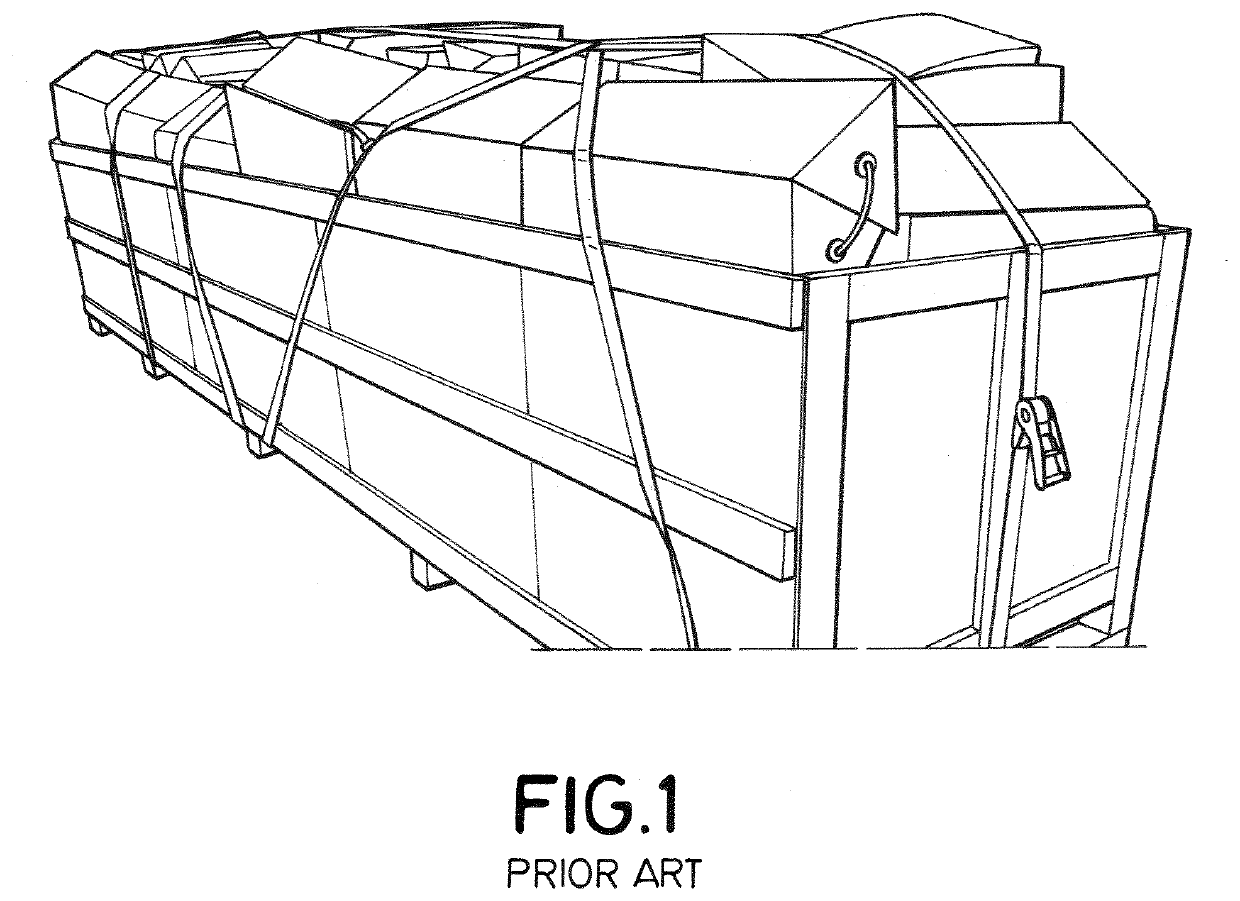
[0038]FIG. 1 illustrates a container packed with helical strakes made of polystyrene foam representing a conventional art helical strake set way of transport. It can be clearly seen a significant volume is needed to transport these helical strakes set, requiring containers of an approximate volume of 10 m3.

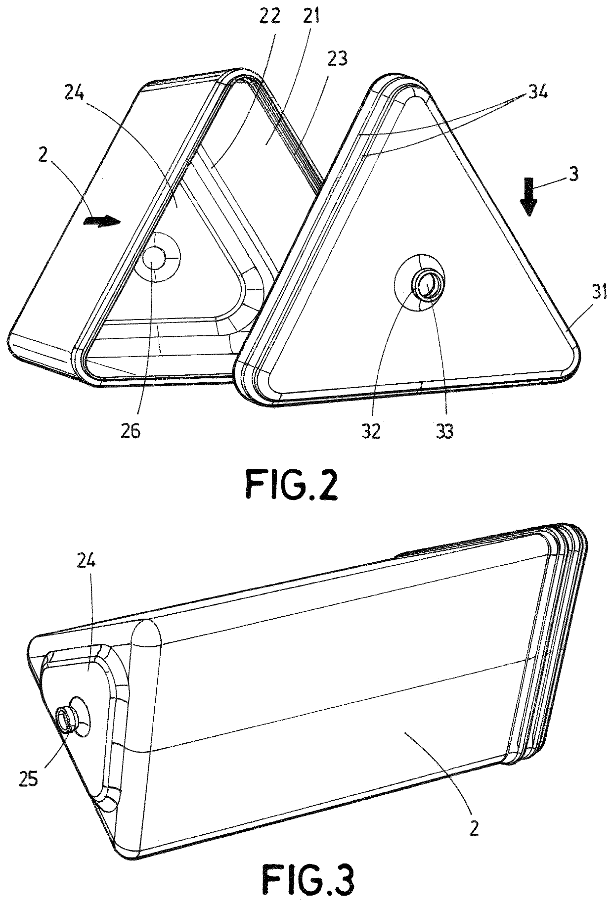
[0039]FIG. 2 illustrates a perspective view of an unattached segment (1) of a helical strake set (10) according to an embodiment of the invention.

[0040]It is clearly shown that each segment (1) comprises a main body (2) of hollow pyramidal configuration with a wide polygonal end (21) and a narrow polygonal end (22).

[0041]In an embodiment, the main body (2) further comprises a narrow polygonal portion (24) fitted in the narrow polygonal end (22) forming one rigid piece said main body (2) and comprising a first through hole (26). In an al...


PUM


Abstract

Provided is a helical strake set to reduce vortex induced vibrations of a tower, intended to be transported unassembled in a container, including a plurality of identical attachable segments, wherein each segment includes a main body of hollow pyramidal configuration including a wide polygonal end a narrow polygonal end and a narrow polygonal portion firmly attached to the narrow polygonal end, and each segment further including a cap including a wide polygonal portion able to fit in the wide polygonal end by a fastening element, wherein all main bodies and caps are able to be piled in one into another in a container yielding a significant reduction in seaborn transport volume and later assembled on site to reduce vortex induced vibrations of a tower.

Description

CROSS-REFERENCE TO RELATED APPLICATIONS[0001]This application claims priority to PCT Application No. PCT / EP2020 / 056441, having a filing date of Mar. 11, 2020, which is based off of EP Application No. 19380011.7, having a filing date of Jun. 17, 2019, the entire contents both of which are hereby incorporated by reference.FIELD OF TECHNOLOGY[0002]The following is included in the technical field of helical strakes to reduce vortex induce vibrations of a tower, especially for wind turbine's towers experiencing vortex amplification accelerations and resonance. More in particular, it relates to a helical strake set comprising attachable segments intended to be arranged and transported in a seaborne container to be later assembled and installed on the tower, achieving great volume reduction and space optimization during transport.BACKGROUND[0003]Wind turbines comprise a tower and a nacelle placed on top of that tower, whereby the nacelle is equipped with a rotor which rotates due to the im...

Claims


Application Information

Patent Timeline
Patent Type & Authority Applications(United States)
IPC IPC(8): F03D13/40F03D13/20
CPCF03D13/40F03D13/20F05B2260/964F05B2250/25F05B2260/02F05B2240/912F05B2250/21F05B2250/11F05B2240/122Y02E10/72Y02E10/728
Inventor OSORIO MARTINEZ, JUAN MANUELSEÑAS PEREZ, VICENTEYABAR BASTERRA, JESUS ANGEL
Owner GAMESA INNOVATION & TECH SA
Why Eureka
Try Eureka