Selecting an image analysis area based on a comparison of dynamicity levels

Pending Publication Date: 2022-10-06
SIGNIFY HLDG BV
View PDF0 Cites 0 Cited by
  • Summary
  • Abstract
  • Description
  • Claims
  • Application Information

AI Technical Summary

Benefits of technology

[0013]Although an analysis area with a higher level of dynamicity may regularly be preferred over an analysis area with a lower level of dynamicity, there are also situations where an analysis area with a higher level of dynamicity is not preferred, e.g. because slower dynamics are more optimal for ambiance light. Furthermore, an analysis area in which changes happen mostly in brightness, while the overall video content has more colorful dynamics, is not optimal either. By selecting analysis areas based on a comparison of their levels of dynamicity with the level of dynamicity of the video frames, the dynamicity of the light effects and the dynamicity of the video content may be aligned. This helps in making the light effects match the video content, e.g. of the video game.

Problems solved by technology

A drawback of this approach is that for video games, the determined light effects are regularly perceived as not matching the video content of the video game.

Method used


Image

  • Selecting an image analysis area based on a comparison of dynamicity levels
  • Selecting an image analysis area based on a comparison of dynamicity levels
  • Selecting an image analysis area based on a comparison of dynamicity levels

Examples


first embodiment

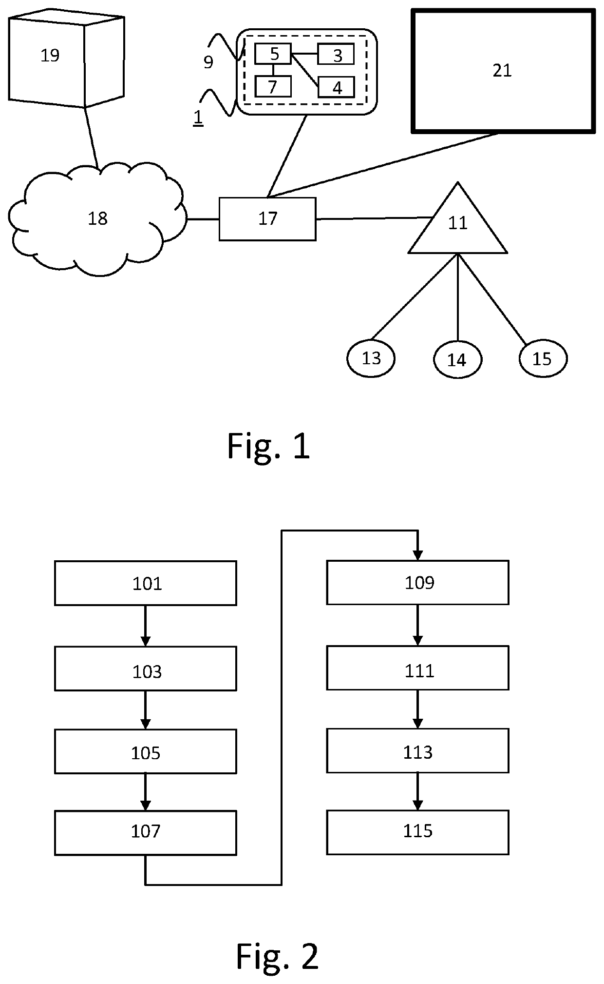
[0062]the method of determining image characteristics from an analysis area in video content is shown in FIG. 2. The image characteristics are used to determine one or more light effects to be rendered on one or more lighting devices while the video content is rendered on a display device. A step 101 comprises obtaining video frames. A step 103 comprises determining a first level of dynamicity in the video frames. A step 105 comprises determining a second level of dynamicity in each of a plurality of analysis areas in the video frames. A step 107 comprises comparing each of the second dynamicity levels with the first dynamicity level.

[0063]A step 109 comprises selecting a subset of the analysis areas based on the comparisons. A step 111 comprises determining image characteristics from the subset of analysis areas in the video content. A step 113 comprises determining one or more light effects based on the image characteristics. A step 115 comprises controlling the one or more lighti...

second embodiment

[0078]the method of determining image characteristics from an analysis area in video content is shown in FIG. 9. In the embodiment of FIG. 9, step 103 of FIG. 3 comprises a sub step 131, step 105 of FIG. 3 comprises a sub step 133 and step 109 of FIG. 3 comprises a sub step 135. The first dynamicity level determined in step 131 represents an overall dynamicity of the video frames and is determined per pixel or per region of pixels.

[0079]In steps 131 and 133, the first level of dynamicity is determined in the video frames and the second level of dynamicity is determined in each of a plurality of analysis areas in the video frames, respectively. In steps 131 and 133, the first dynamicity level and / or the second dynamicity levels are determined by comparing successive ones of the video frames.

[0080]Steps 131 and 133 comprise determining chromaticity and / or brightness differences in these successive video frames, specifically cumulative frame differences. In these steps, the difference ...

third embodiment

[0082]the method of determining image characteristics from an analysis area in video content is shown in FIG. 10. In the embodiment of FIG. 10, step 103 of FIG. 3 comprises a sub step 141 and step 105 of FIG. 3 comprises a sub step 143. The first dynamicity level determined in step 141 represents an overall dynamicity of the video frames and is determined per pixel or per region of pixels.

[0083]In steps 141 and 143, the first level of dynamicity is determined in the video frames and the second level of dynamicity is determined in each of a plurality of analysis areas in the video frames, respectively. In steps 141 and 143, the first dynamicity level and / or the second dynamicity levels are determined by comparing successive ones of the video frames.

[0084]Steps 141 and 143 comprise detecting edges in each of the successive ones of the video frames and determining changes in the detected edges between the successive ones of the video frames. Steps 141 and 143 are like steps 131 and 133...


PUM


Abstract

A system (1) is configured to determine a first level of dynamicity in video frames, determine a second level of dynamicity in each of a plurality of analysis areas (52,73) in the video frames, compare each of the second dynamicity levels with the first dynamicity level, select a subset (73) of the analysis areas based on the comparisons, determine image characteristics from the subset of analysis areas in the video content, determine one or more light effects based on the image characteristics, and control one or more lighting device to render the one or more light effects and / or store a light script specifying the one or more light effects. The light effects are to be rendered while the video content is rendered on a display device (9).

Description

FIELD OF THE INVENTION[0001]The invention relates to a system for determining image characteristics from an analysis area in video content, said image characteristics being used to determine one or more light effects to be rendered on one or more lighting devices while said video content is rendered on a display device.[0002]The invention further relates to a method of determining image characteristics from an analysis area in video content, said image characteristics being used to determine one or more light effects to be rendered on one or more lighting devices while said video content is rendered on a display device.[0003]The invention also relates to a computer program product enabling a computer system to perform such a method.BACKGROUND OF THE INVENTION[0004]Philips' Hue Entertainment and Hue Sync are gaining popularity. Philips Hue Sync enables the rendering of light effects based on the content that is played on a computer, e.g. video games. A dynamic lighting system can dra...

Claims


Application Information

Patent Timeline
Patent Type & Authority Applications(United States)
IPC IPC(8): G06T7/215H04N9/73H05B47/155
CPCG06T7/215H04N9/73H05B47/155H04N5/57G06V20/46
Inventor ALIAKSEYEU, DZMITRY VIKTOROVICHMASON, JONATHAN DAVID
Owner SIGNIFY HLDG BV
Why Eureka
Try Eureka