Method and arrangement for controlling the temperature of the outstream flow from a heat exchanger and measuring produced heat

a heat exchanger and outstream flow technology, applied in the field of methods and, can solve the problems of significant recice of calcific risk in beat exchangers, and achieve the effect of improving the consistency of hot tap water temperature and quick and stable control equipmen

Inactive Publication Date: 2004-08-05
LINDGREN
View PDF13 Cites 12 Cited by
  • Summary
  • Abstract
  • Description
  • Claims
  • Application Information

AI Technical Summary

Benefits of technology

[0014] The purpose of the invention is to obtain a rapid and stable controlling equipment in hea exchanging systems, where large variations may occur on the primary side as far as inbound temperatures and differental pressure are concerned, where an improved consistency of the hot tap water temperature on the consumer side is achieved without the necessity for feedback of the actual temperature value from the secondary side, for actually keeping ete temperature constant.
[0016] Through the invention, the risk for oscillations in the temperature is eliminated on the secondary side, which in a district heaig plant corresponds to a hot tap water circuit. Often, a district heating plot also has hew exchange circuits for radiator and ventilation systems, for which te invention is wall adapted. For this type of systems, the dynamics of load changes are often slower.
[0017] The invention provides improved load adaptability, independent of consumer size. Also, the risk for calcific in beat exchangers is reciced significantly, since faster cool systems with higher Con can counter temp ure peaks above 60.degree. C.
[0019] In most district heating systems, the invention also entails that the control system may be installed without adjustment of regulatory parameters, which strongly reduces the time required for installation and service / fine tuning.

Problems solved by technology

Also, the risk for calcific in beat exchangers is reciced significantly, since faster cool systems with higher Con can counter temp ure peaks above 60.degree. C.

Method used


Image

  • Method and arrangement for controlling the temperature of the outstream flow from a heat exchanger and measuring produced heat
  • Method and arrangement for controlling the temperature of the outstream flow from a heat exchanger and measuring produced heat
  • Method and arrangement for controlling the temperature of the outstream flow from a heat exchanger and measuring produced heat

Examples


Embodiment Construction

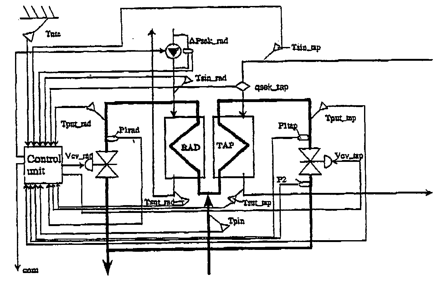
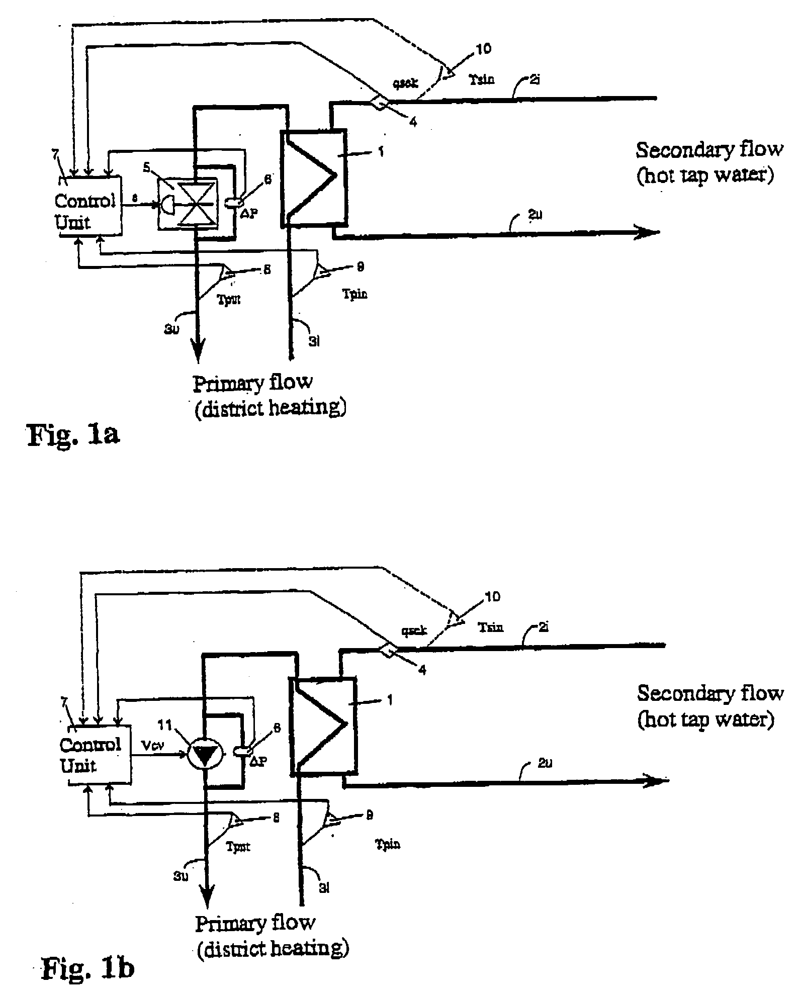
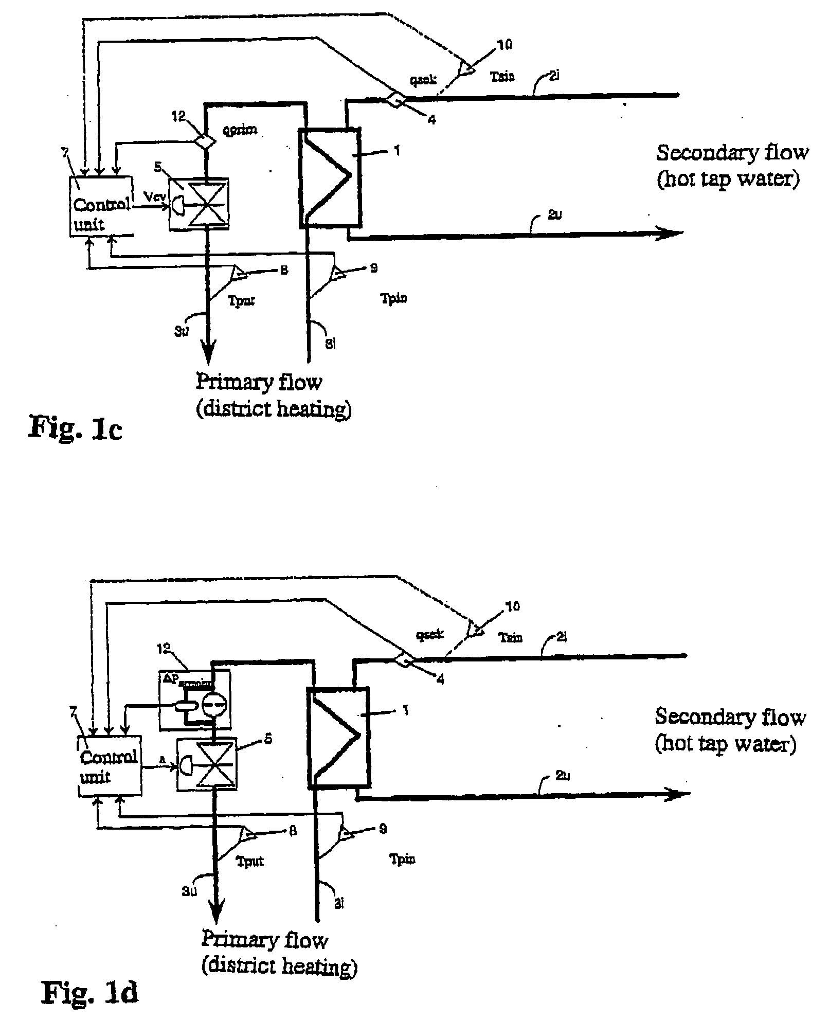
[0030] FIG. 1a shows an impentation of the invenition in a district heating station of a cousider. The station ompnrises a boat exchanger 1, compnsuig a circuit 3, and a secondary circuit 2. The inbound primary flow 3i to the circuit 3 is constituted by hot water from the central heating system, while the outbound primary flow 3u is constitited by recycled water. The seco flow 2i of the secondary ciit 2 is consti d by incoming fresh water, heated in the heat exchanger 1, while the tapped secondary flow 2i is constituted by heated hot tap water, conductd to the taps of the end consumer or the customer. When the temperature of the inbound secondary flow 2i can not be assumed to be otherwise known (for instance, tough being constant and known beforehand), a temperature gauge is arranged in the inbound flow 2i (shown with dashed lines in the figures).

[0031] A flow meter 4 is arranged in the secondary circuit 2i-2u, preferably on the opening side, and the signals of which the flow meter ...


PUM

PropertyMeasurementUnit
temperatureaaaaaaaaaa
densityaaaaaaaaaa
pressureaaaaaaaaaa

Abstract

Process and device for controlling the temperature of an outbound secondary flow in a secondary circuit from a heat exchanger by a primary flow in a primary circuit, via a member that regulates the primary flow, influenced by a control unit. The enthalpy difference between inbound and outbound primary flow to and from the heat exchanger and the secondary flow are determined. The flow in the primary circuit is determined, and the parameters are supplied to the control unit for controlling the member, whereby the primary flow is controlled in dependence of the secondary flow, so that power supplied to the heat exchanger substantially equals the sum of the power needed to raise the temperature of the secondary flow from the initial temperature to the desired outbound temperature; the assumed power requirement for compensating for energy stored in the heat exchanger; and the assumed leak power from the heat exchanger.

Description

[0001] The present invention relates to a method and a device for controlling the temperature of at least one outbound secondary flow in a secondary circuit from a heat exchanger through a pi flow in a p a circuit, via a control member which can be affected by a control unit, which member regulates the primary flow. The invention also relates to a method for measuring yielded power and hea quantity.BACKGROUND OF THE INVENTION AND THE PROBLEM[0002] During delivery of hot tap water in district heafing station, a priary flow of centrally heated water, which is conducted into a heat exchanger, where a secondary flow of hot tap water is heated to a constant consuming temperture in the heat exchanger. Control of the constant consuming temperature on the secondary side have been obtained in the district heating station, either through aunomatic mechanical, or through electonic control devices, which control the temperature on the basis of correction of the difference between desired and ac...

Claims


Application Information

Patent Timeline
Patent Type & Authority Applications(United States)
IPC IPC(8): F24D10/00F24D19/10F28F27/02
CPCF24D10/003F24D19/10F24D19/1051Y02E20/14F28F27/02F24D10/00Y02B30/17
Inventor LINDGREN
Owner LINDGREN
Why Eureka
Try Eureka