
Communication device, communication method, and non-transitory computer-readable recording medium

Pending Publication Date: 2022-10-06
WOVEN PLANET HLDG INC
View PDF0 Cites 0 Cited by
  • Summary
  • Abstract
  • Description
  • Claims
  • Application Information

AI Technical Summary

Benefits of technology

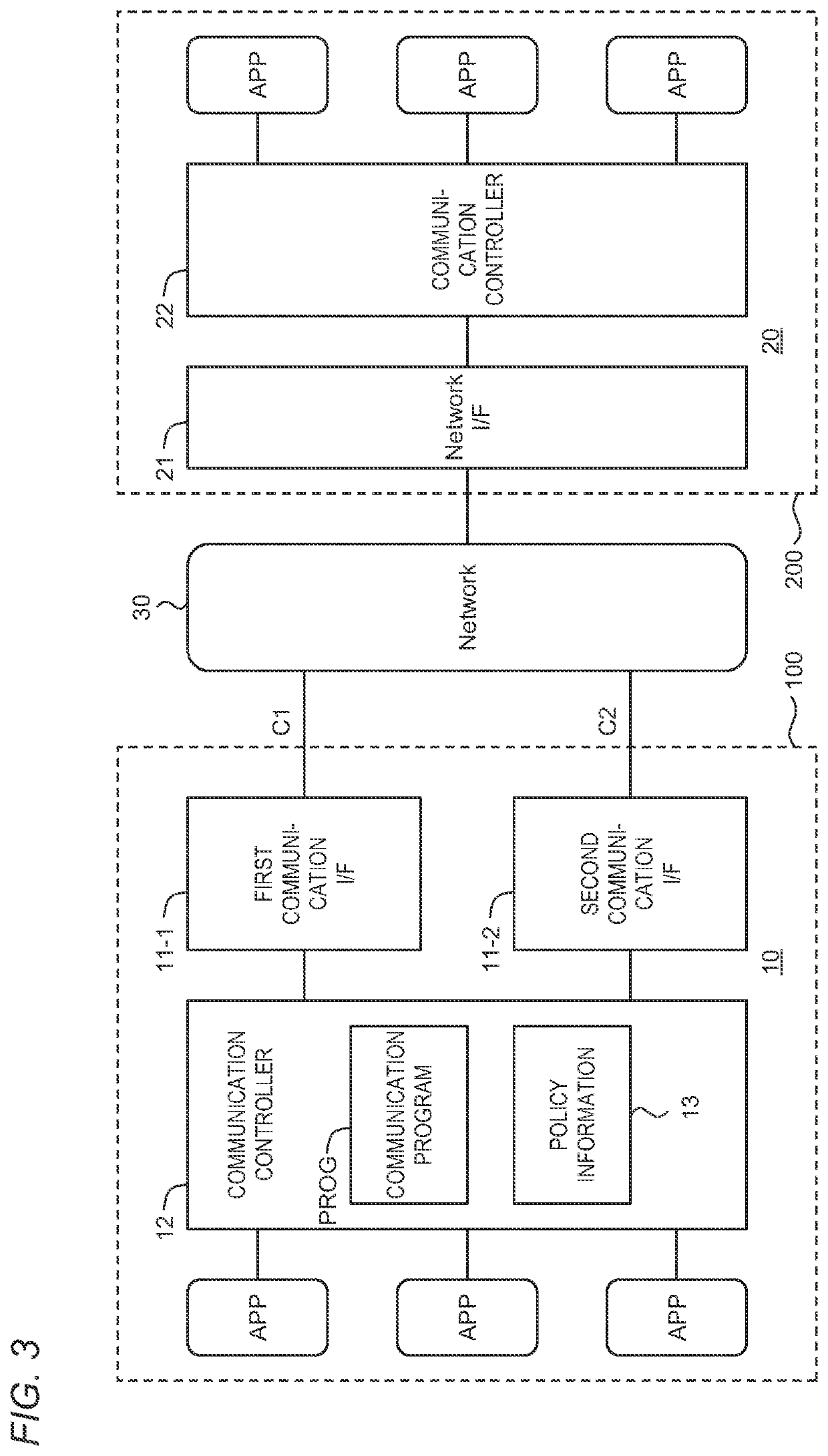
The patent text describes a technique for a moving body, like a vehicle or robot, to communicate with external devices using multiple communication lines. The technique prioritizes certain data over others, reducing the number of lines needed and lowering costs. The allocation between data and lines is dynamically controlled based on the speed of the first line, allowing for flexible and efficient communication based on the situation. The technical effect is a more flexible and cost-effective way of streaming data communication for moving bodies.

Problems solved by technology

However, increase in the number of communication lines used simultaneously causes increase in a communication cost accordingly.

Method used


Image

  • Communication device, communication method, and non-transitory computer-readable recording medium
  • Communication device, communication method, and non-transitory computer-readable recording medium
  • Communication device, communication method, and non-transitory computer-readable recording medium

Examples


first example

4-1. First Example

[0086]FIG. 6 is a timing chart for explaining a first example of the dynamic allocation control process. In the first example, the dynamic allocation control process intended to secure the data quality as much as possible will be described. That is, a communication requirement in the first example is “data quality-oriented.”

[0087]In a period before a time t1, the first communication rate R1 of the first communication line C1 is equal to or higher than a first threshold Th1. In this case, both the first streaming data S1 and the second streaming data S2 can be transmitted via the first communication line C1 without reducing the data quality. Therefore, the communication controller 12 allocates both the first streaming data S1 and the second streaming data S2 to the first communication line C1 having the higher line priority. The congestion control is not performed for the first streaming data S1 and the second streaming data S2. Therefore, an excellent data quality ...

second example

4-2. Second Example

[0099]FIG. 8 is a timing chart for explaining a second example of the dynamic allocation control process. In the second example, the dynamic allocation control process intended to reduce the communication cost as much as possible will be described. That is, the communication requirement in the second example is “communication cost-oriented.”

[0100]In a period before a time t1, the first communication rate R1 of the first communication line C1 is equal to or higher than a first threshold Th1. In this case, the communication controller 12 allocates both the first streaming data S1 and the second streaming data S2 to the first communication line C1, as in the case of the first example described above. It is thus possible not only to secure the excellent data quality but also to reduce the communication cost.

[0101]In a period from the time t1 to a time t2, the first communication rate R1 of the first communication line C1 is lower than the first threshold Th1 and is eq...

third example

4-3. Third Example

[0112]FIG. 10 is a timing chart for explaining a third example of the dynamic allocation control process. The third example is a modification of the second example. A description overlapping the case of the second example will be omitted as appropriate.

[0113]In the period from the time 13 to the time t4, the first communication rate R1 of the first communication line C1 is lower than the third threshold Th3 and is equal to or higher than the fourth threshold Th4. In this case, the communication controller 12 allocates the second streaming data S2 to the first communication line C1, and performs the congestion control for the second streaming data S2. On the other hand, the communication controller 12 allocates the first streaming data S1 to the second communication line C2. The congestion control is not performed for the first streaming data S1. As a result, the quality of the first streaming data S1 having the higher streaming priority is secured in preference to ...


PUM


Abstract

A communication device is installed on a moving body and capable of communicating with an external device via a plurality of communication lines. The communication device includes a controller. The controller acquires a plurality of streaming data to be transmitted to the external device and dynamically controls an allocation relationship between the plurality of streaming data and the plurality of communication lines. The plurality of communication lines include a first communication line and a second communication line having a lower priority than the first communication line. The controller dynamically controls the allocation relationship based on a first communication rate being a communication rate of the first communication line while preferentially allocating the plurality of streaming data to the first communication line in preference to the second communication line.

Description

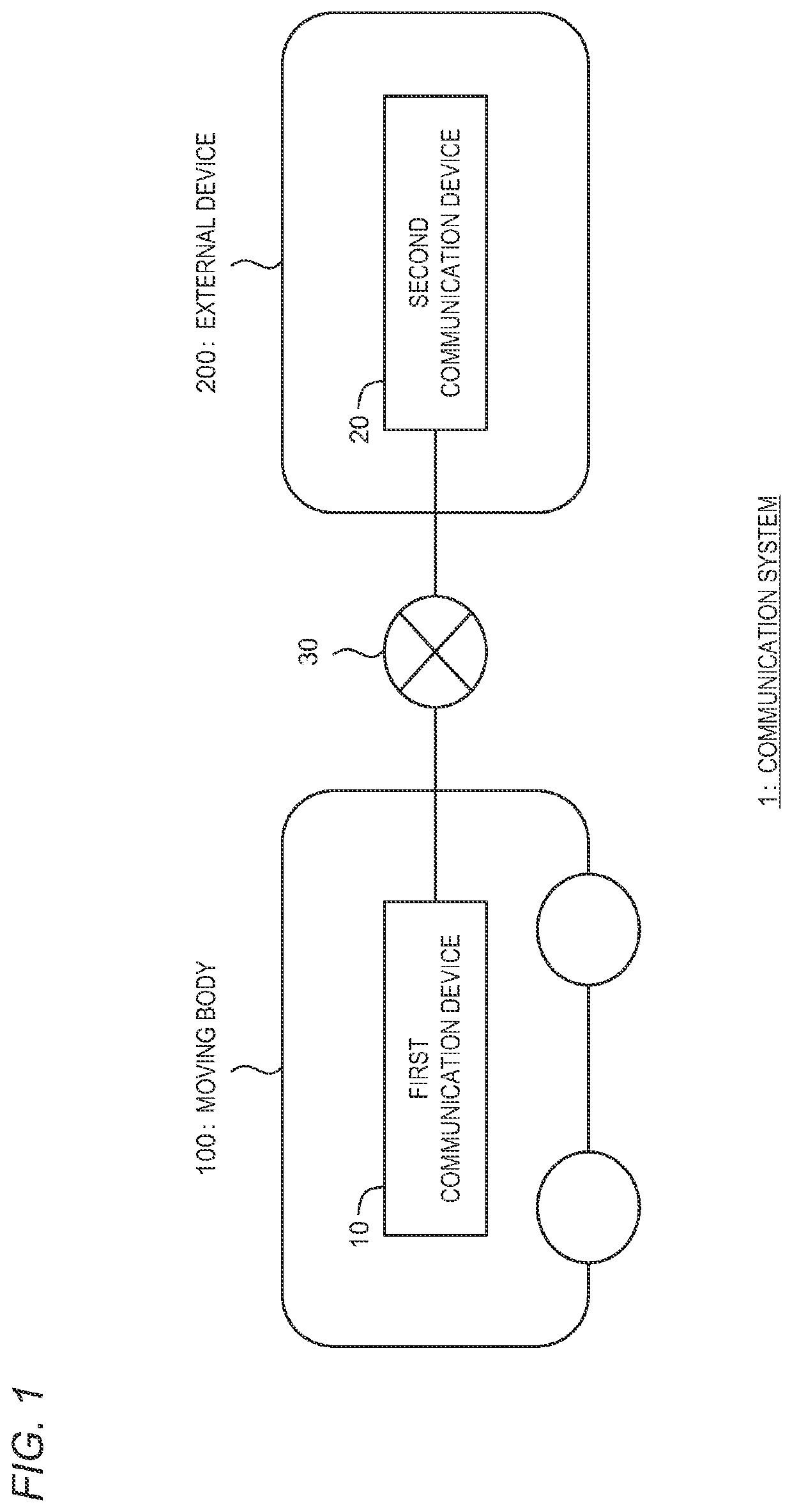
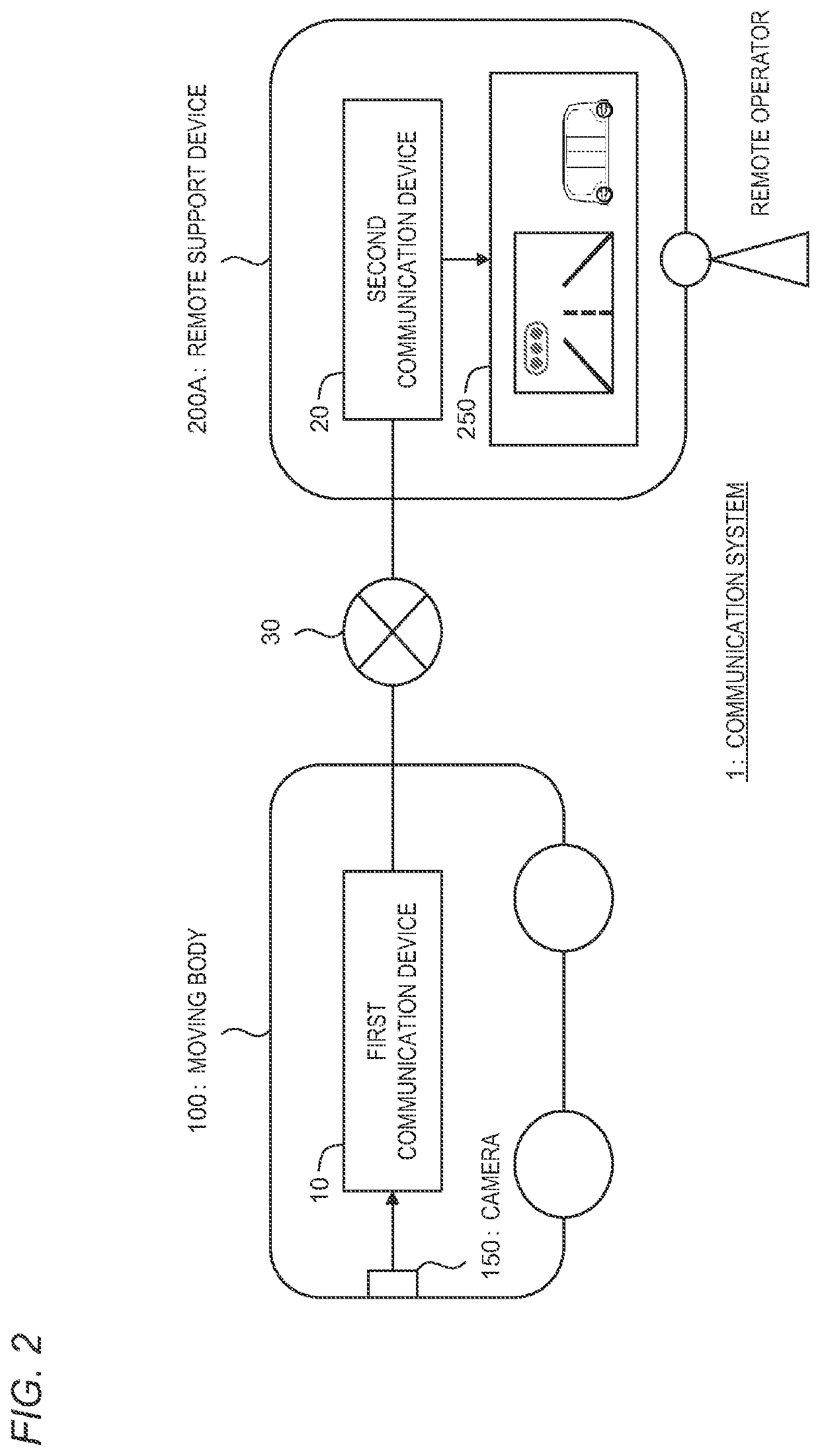
CROSS-REFERENCE TO RELATED APPLICATION[0001]This application claims priority to Japanese Patent Application No. 2021-064861 filed on Apr. 6, 2021, the entire contents of which are incorporated by reference herein.BACKGROUNDTechnical Field[0002]The present disclosure relates to a communication technique applied to a moving body.Background Art[0003]Patent Literature 1 discloses an in-vehicle communication device. The in-vehicle communication device supports both a mobile communication method and a WiFi communication method. When an abnormality of the vehicle is detected, the in-vehicle communication device transmits numerical data and image data indicating a vehicle travel status to a specified server. At this time, the in-vehicle communication device transmits the numerical data by the mobile communication method and transmits the image data by the WiFi communication method.[0004]Patent Literature 2 discloses a method of performing a communication between communication devices provid...

Claims


Application Information

Patent Timeline
IPC IPC(8): H04L47/80H04L47/12
CPCH04L47/805H04L47/12H04W28/0268H04W28/0231H04W28/0289H04W76/15
Inventor WATANABE, TOSHINOBU
Owner WOVEN PLANET HLDG INC
Learn More