Gripping position determination device, gripping position determination system, gripping position determination method, and recording medium

a technology of gripping position and determination device, which is applied in the direction of programmed manipulators, instruments, programme control, etc., can solve the problems of unstable gripping state and increase of lateral force, and achieve the effect of stable gripping

Pending Publication Date: 2022-10-13
HONDA MOTOR CO LTD
View PDF0 Cites 0 Cited by
  • Summary
  • Abstract
  • Description
  • Claims
  • Application Information

AI Technical Summary

Benefits of technology

[0019](10) a recording medium, recording a program according to one aspect of the disclosure causes a computer of a gripping position determination device of a robot hand having a plurality of multi joint fingers to estimate, from a predictive control of a gripping force when an object is gripped by at least two of the multiple fingers, a frictional force between one of the gripping fingers and the object, and calculate a frictional force distribution where gripping of the object is possible on a surface of the object based on a value related to a frictional force calculated by using the estimated frictional force; select, from the frictional force distribution, at least one grippable region; and calculate, from the selected grippable region, a gripping position where stable gripping of the object is possible.

Problems solved by technology

As shown in FIG. 13, when the inter-finger gap increases, the lateral force increases and the gripping state becomes unstable.

Method used


Image

  • Gripping position determination device, gripping position determination system, gripping position determination method, and recording medium
  • Gripping position determination device, gripping position determination system, gripping position determination method, and recording medium
  • Gripping position determination device, gripping position determination system, gripping position determination method, and recording medium

Examples


first embodiment

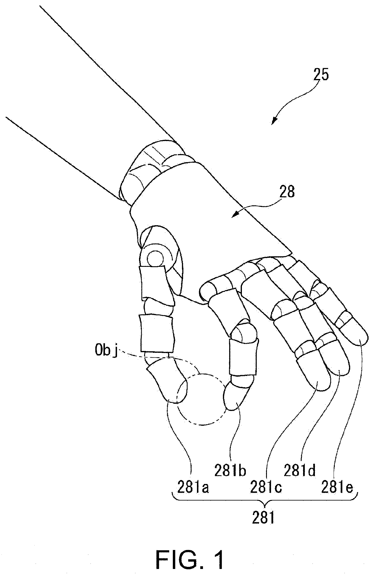
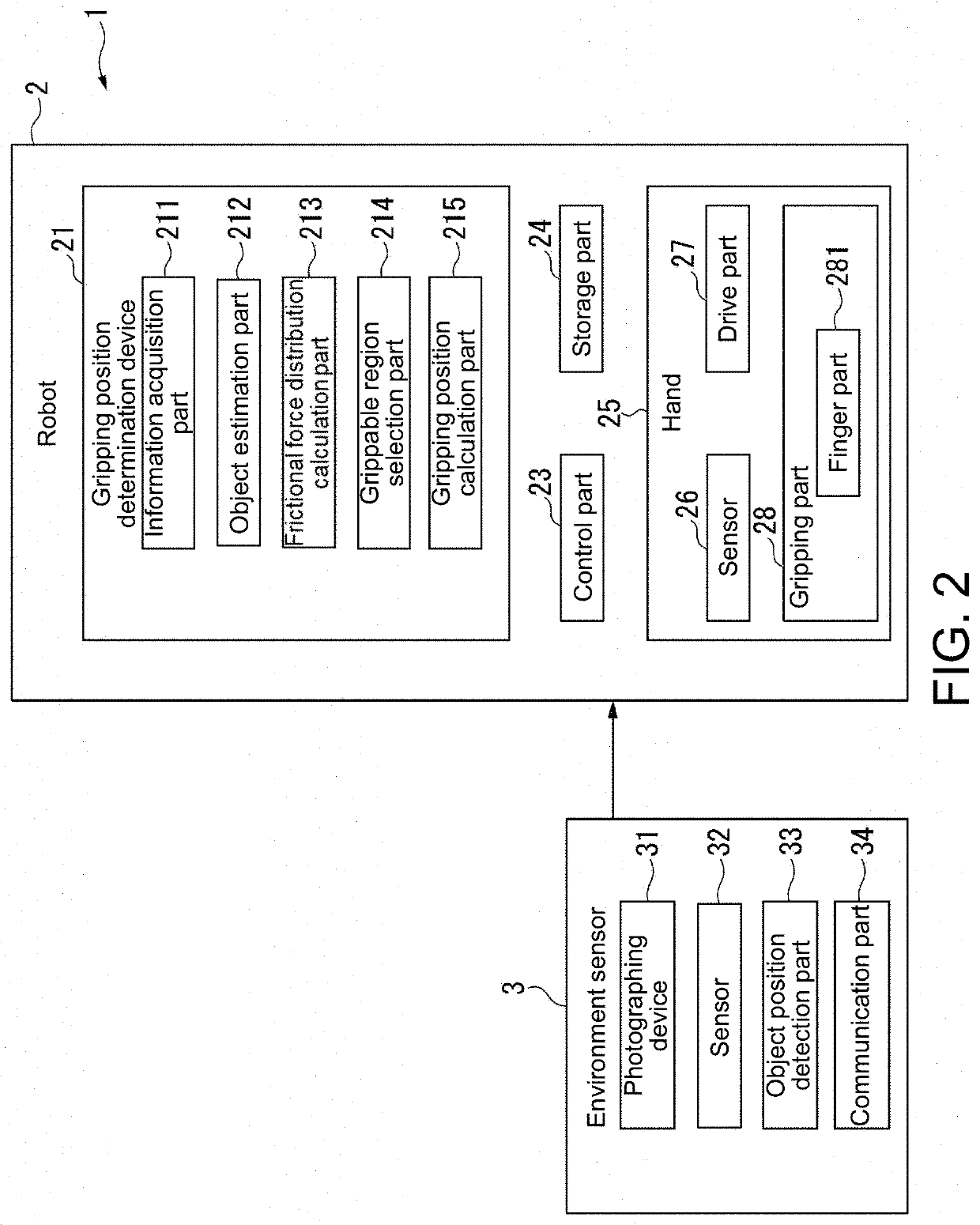
[0041]FIG. 1 is a block diagram showing a configuration example of a gripping position determination system according to the present embodiment. As shown in FIG. 2, a gripping position determination system 1 includes a robot 2 and an environment sensor 3.

[0042]The robot 2 includes a gripping position determination device 21, a control part 23, a storage part 24, and a hand 25 (robot hand). The robot 2 may further include legs, a head, a torso, a waist, and the like in addition to the hand 25, for example. Further, the robot 2 is provided with a power supply (not shown). The power supply supplies electric power to each part of the robot 2. The power supply may include, for example, a rechargeable battery or a charging circuit.

[0043]The gripping position determination device 21 includes an information acquisition part 211, an object estimation part 212, a frictional force distribution calculation part 213, a grippable region selection part 214, and a gripping position calculation part...

modification example

[0100]Here, an example of searching for a gripping position (correction position) to be corrected by using information related to the shape of an object will be described with reference to FIGS. 6 to 8.

[0101]FIG. 6 is a diagram showing an example of an initial gripping position, a frictional force distribution, and a correction position when gripping a smartphone having a curved surface at an edge. In the example of FIG. 6, in a state where the robot 2 grips the smartphone with the thumb 281a, the index finger 282b, and the middle finger 282c, the gripping position of the thumb 281a is corrected so that the smartphone may be gripped more stably. An arrow g101 shows a force acting on the surface of the object Obj by the index finger 282b. An arrow g102 shows a force acting on the surface of the object Obj by the middle finger 282c. An arrow g103 shows a force acting on the surface of the object Obj by the thumb 282a at the initial position.

[0102]In this case, the gripping force distr...

second embodiment

[0114]According to the present embodiment, in order to further maintain the posture and movement of the object in a specific state, a gripping position reflecting a specific condition (for example, gravity) is calculated. In this case, the gripping position is not always the position where the frictional force is minimized. In the present embodiment, a state in which the object is gravitationally balanced and may be gripped, a state in which the object may be gripped even if the posture of the object is tilted or the like is included.

[0115]FIG. 9 is a block diagram showing a configuration example of the gripping position determination system according to the present embodiment. As shown in FIG. 9, a gripping position determination system 1A includes a robot 2A and the environment sensor 3.

[0116]The robot 2A includes a gripping position determination device 21A, a control part 23, a storage part 24, and the hand 25.

[0117]The gripping position determination device 21A includes the inf...


PUM


Abstract

The disclosure provides a gripping position determination device, a gripping position determination system, a gripping position determination method, and a recording medium. The gripping position determination device for a robot hand having a plurality of multi joint fingers includes: a frictional force distribution calculation part estimating, from a predictive control of a gripping force when an object is gripped by at least two fingers, a frictional force between one of the gripping fingers and the object, and calculates a frictional force distribution where grapping of the object is possible on a surface of the object based on a value related to a frictional force calculated by using the estimated frictional force; a grippable region selection part selecting, from the frictional force distribution, at least one grippable region; and a gripping position calculation part calculating, from the selected grippable region, a gripping position where stable gripping of the object is possible.

Description

CROSS-REFERENCE TO RELATED APPLICATION[0001]This application claims the priority benefits of Japanese application no. 2021-060662, filed on Mar. 31, 2021. The entirety of the above-mentioned patent application is hereby incorporated by reference herein and made a part of this specification.BACKGROUNDTechnical Field[0002]The disclosure relates to a gripping position determination device, a gripping position determination system, a gripping position determination method, and a recording medium.Related Art[0003]A control device to make a robot grip an object has been proposed. As such a control device, a method has been proposed to search for a higher quality gripping point by tentatively determining a physically contactable gripping point, determining a gripping force in consideration of the balance of forces, and evaluating the quality of the gripping force as a volume of the envelope of the gripping force (see, for example, Patent Literature 1).[0004]Further, according to the techni...

Claims


Application Information

Patent Timeline
Patent Type & Authority Applications(United States)
IPC IPC(8): B25J9/16
CPCB25J9/1653B25J9/1633B25J9/1612B25J15/0009G05B2219/39505G05B2219/39536G05B2219/40155B25J9/1697G05B2219/40551
Inventor YOSHIHIRA, MASANORIHASEGAWA, TADAAKI
Owner HONDA MOTOR CO LTD
Why Eureka
Try Eureka