Air-cooling device

a cooling device and air technology, applied in lighting and heating apparatus, ventilation systems, heating types, etc., can solve the problems of reducing cooling efficiency, difficult for the air that has passed through the vicinity of the end of the opening to flow toward the radiator core, and difficult for the air that has passed through the radiator core to pass efficiently. , to achieve the effect of efficient cooling

Pending Publication Date: 2022-10-13
TOYOTA JIDOSHA KK +1
View PDF0 Cites 0 Cited by
  • Summary
  • Abstract
  • Description
  • Claims
  • Application Information

AI Technical Summary

Benefits of technology

[0004]An air-cooling device mounted on a vehicle includes a fan. When a vehicle stops or travels at a low speed, the fan causes air to flow into a radiator core. When the fan causes the air to flow into the radiator core, a flow rate of the air flowing into the radiator core is low, which is different from when a vehicle travels at a high speed. Therefore, the air at a high temperature that has passed through the radiator core may pass through a clearance between the radiator and the duct, and flow back into the duct. When such a backflow occurs, a temperature of the air flowing into the radiator core increases, so that cooling efficiency is reduced.
[0007]In the air-cooling device according to the above aspect, the frame is disposed to extend from a position on one side of a straight line to a position on an opposite side of the straight line, the straight line extending rearward from the end of the opening. Therefore, when the fan is operated, it is difficult for the air that has passed through the vicinity of the end of the opening to flow toward the radiator core. Therefore, the air that has passed through the vicinity of the end of the opening flows toward the space between the connecting portion and the straight line, and flows in a spiral manner in the vicinity of the connecting portion. Therefore, it is difficult for the air that has passed through the radiator core to flow into the clearance at the connecting portion. Therefore, the air that has passed through the radiator core is restrained from passing through the clearance at the connecting portion and flowing back into the duct. As a result, according to this air-cooling device, the radiator core can be efficiently cooled.

Problems solved by technology

When such a backflow occurs, a temperature of the air flowing into the radiator core increases, so that cooling efficiency is reduced.
Therefore, when the fan is operated, it is difficult for the air that has passed through the vicinity of the end of the opening to flow toward the radiator core.
Therefore, it is difficult for the air that has passed through the radiator core to flow into the clearance at the connecting portion.

Method used


Image

  • Air-cooling device
  • Air-cooling device
  • Air-cooling device

Examples


first embodiment

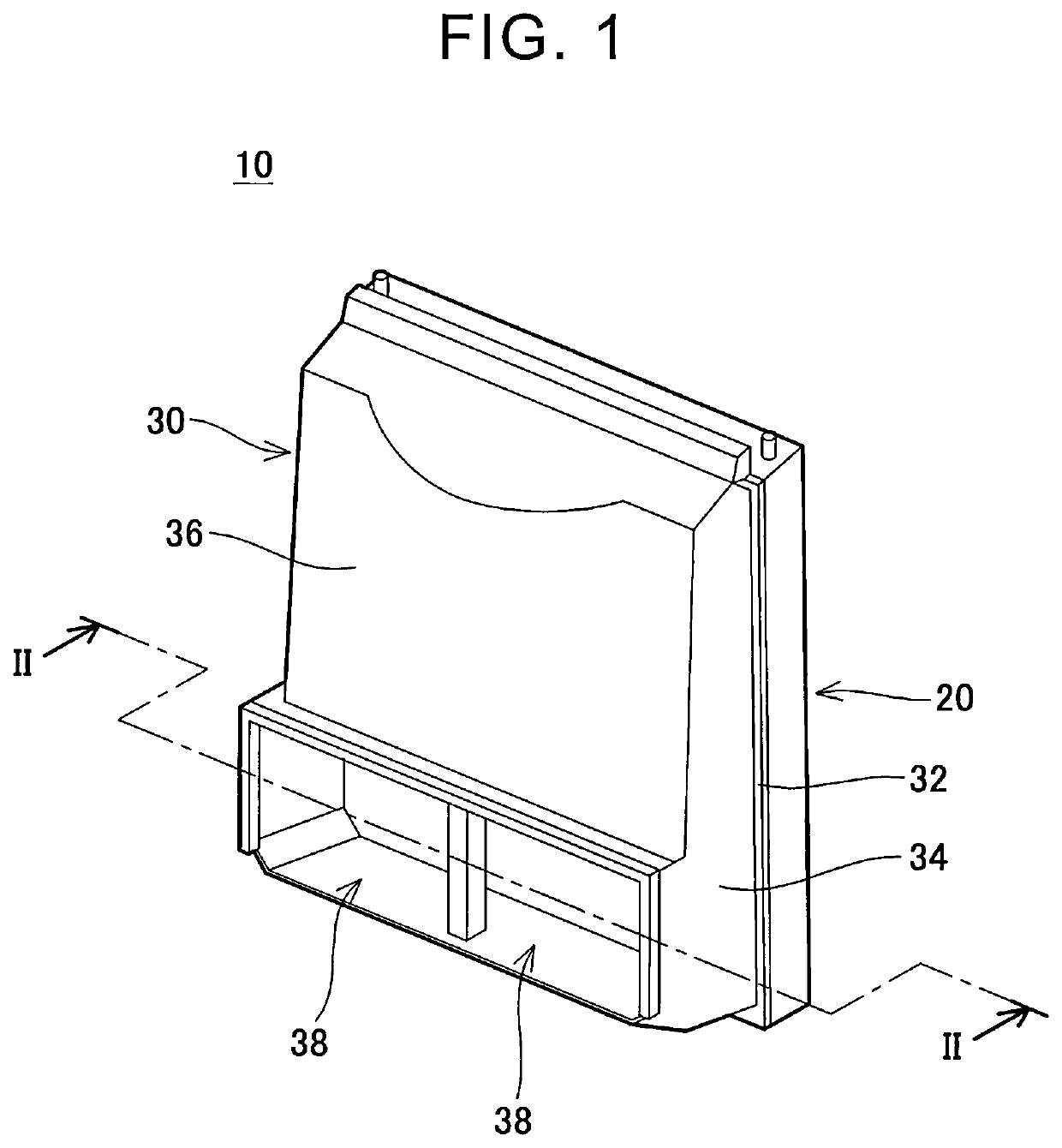
[0017]An air-cooling device 10 according to a first embodiment shown in FIG. 1 is installed in a front compartment of a vehicle. The air-cooling device 10 is disposed rearward of a front grille. The air-cooling device 10 includes a radiator 20 and a duct 30.

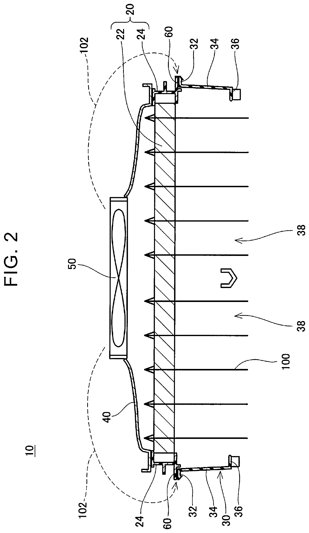
[0018]A coolant flows inside the radiator 20. The radiator 20 cools the coolant by heat exchange between the coolant and air. As shown in FIG. 2, the radiator 20 includes a radiator core 22 and a radiator tank 24. The radiator core 22 is made of a metal (for example, aluminum). The radiator core 22 includes a plurality of tubes in which the coolant flows and a plurality of cooling fins connected to the tubes. A flow path in which the air flows is provided (formed) by spaces between the tubes. When the air passes through the radiator core 22, the coolant in the radiator core 22 is cooled. The radiator tank 24 is connected to an outer peripheral portion of the radiator core 22. Specifically, the radiator tank 24 is connected to sid...

second embodiment

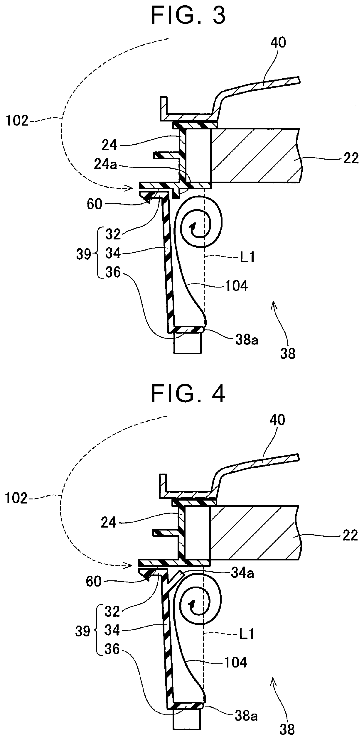
[0023]An air-cooling device according to a second embodiment shown in FIG. 4 is different from the air-cooling device 10 according to the first embodiment in the position of the rib. Other configurations of the air-cooling device according to the second embodiment is equivalent to those of the air-cooling device 10 according to the first embodiment. As shown in FIG. 4, the air-cooling device according to the second embodiment does not include a rib on the front surface of the radiator tank 24, and includes a rib 34a on the inner surface of the side wall 34 of the duct 30. The rib 34a projects from the inner surface of the side wall 34 to the inner side. The rib 34a projects (extends) obliquely rearward from the inner surface of the side wall 34. The rib 34a is disposed in the vicinity of the boundary portion 60, and extends along the boundary portion 60.

[0024]In the configuration according to the second embodiment as well, the air easily flows into the space between the straight lin...


PUM


Abstract

An air-cooling device includes a radiator, a duct, and a fan. The radiator includes a radiator core and a frame connected to an outer peripheral portion of the radiator core. The duct is disposed forward of the radiator. The duct includes an opening disposed forward of the radiator core and an air guide that extends from the frame to an end of the opening. The fan causes air to flow from the opening to the radiator core. The frame is disposed to extend from a position on one side of a straight line to a position on an opposite side of the straight line, the straight line extending rearward from the end of the opening. A connecting portion between the frame and the air guide is located at a distance from the straight line.

Description

CROSS-REFERENCE TO RELATED APPLICATION[0001]This application claims priority to Japanese Patent Application No. 2021-065239 filed on Apr. 7, 2021, incorporated herein by reference in its entirety.BACKGROUND1. Technical Field[0002]The technique in the disclosure relates to an air-cooling device.2. Description of Related Art[0003]An air-cooling device disclosed in Japanese Unexamined Patent Application Publication No. 2020-040562 (JP 2020-040562 A) includes a radiator and a duct (that is, an air guide) disposed forward of the radiator. Air flows into a radiator core from an opening of the duct while a vehicle is traveling, so that the radiator core is cooled. By providing the duct, air can be efficiently introduced to the radiator core.SUMMARY[0004]An air-cooling device mounted on a vehicle includes a fan. When a vehicle stops or travels at a low speed, the fan causes air to flow into a radiator core. When the fan causes the air to flow into the radiator core, a flow rate of the air f...

Claims


Application Information

Patent Timeline
Patent Type & Authority Applications(United States)
IPC IPC(8): F24F7/007
CPCF24F7/007B60K11/04B60K11/08
Inventor NISHIOKA, HIDEOISHIKAWATANAKA, HIROKI
Owner TOYOTA JIDOSHA KK
Why Eureka
Try Eureka