Air separation method and apparatus

a separation method and air technology, applied in lighting and heating apparatus, solidification, refrigeration and liquid storage, etc., can solve the problems of reduced oxygen recovery, increased energy added to the plant by the cold compressor, and increased refrigeration demand, so as to reduce energy consumption, increase oxygen recovery, and increase oxygen recovery

Inactive Publication Date: 2018-01-11
PRAXAIR TECH INC
View PDF3 Cites 0 Cited by
  • Summary
  • Abstract
  • Description
  • Claims
  • Application Information

AI Technical Summary

Benefits of technology

[0013]The present invention inherently allows lower power consumption and higher oxygen recoveries than in the prior art by utilizing the second boosted pressure air stream to assist in heating the pumped liquid oxygen stream. As indicated above, the use of cold compression and an expander exhausting into the lower pressure column is inherently efficient from the standpoint of the electrical power and running costs consumed in compressing the air. The drawback in cold compression is that energy is added to the plant by the cold compressor that must be compensated for by an increased refrigeration demand. However, such an increased refrigeration demand requires additional air being sent to the turboexpander exhausting into the lower pressure column. This results in less air being introduced into the higher pressure column and a decrease in the oxygen recovery. The utilization of the second boosted pressure air stream to help in heating the air will result in less of a demand for heating to be supplied by the first boosted pressure air stream at warmer temperatures. This in turn will result in lower flow rates and lower pressures for the first boosted pressure air stream than would otherwise be required. The pressure elevation of the second boosted air stream reduces the flow rate of the second boosted air stream to provide the necessary refrigeration for the plant and compensate for cold compression. As such, the electrical power that would otherwise be consumed in compressing the first boosted pressure air stream is reduced, the air flow to the turboexpander is also reduced and the oxygen recovery is therefore, increased to obtain a better balance between energy consumption and oxygen recovery. Moreover, as will be discussed, this is accomplished without the use of redundant compressor and expander arrangements.
[0016]Oxygen recovery can be increased by removing an argon and oxygen containing stream from the lower pressure column and introducing such stream into an argon column to separate the argon and the oxygen and thereby to produce an oxygen containing liquid as a column bottoms and an argon-rich vapor column overhead. An oxygen containing stream composed of the oxygen containing liquid can be introduced into the lower pressure column to increase the oxygen recovery.
[0017]The cold compressor can be independently driven by a motor. This will also reduce energy consumption because the air when cold will be denser than warmer air and therefore, require less energy to compress the air than would otherwise be required at a warmer temperature. This reduction in electrical power requirement comes at the cost of providing a separate motor. However, this cost will be less than the cost of providing a separate turbine to run the cold compressor. Furthermore, the advantage of coupling the second booster compressor to the turbine is lost if the turbine is instead coupled to the cold compressor. In this regard, the term “independently driven” as used herein and in the claim means driven by a means other than with expansion work directly generated by the expansion of a process stream within the plant. Thus, the cold compressor drive could be by an electric motor or a steam turbine or other external means. In any embodiment, the motor can be a variable speed motor controlled by a variable speed drive. This allows the speed of the motor and therefore, the cold compressor to be reduced during a turndown operation of the cryogenic rectification process when production of the oxygen product stream is also reduced. The term “turndown operation” as used herein and in the claims means any operation of an air separation plant in which the air flow rate of the compressed and purified air entering the plant is reduced to in turn reduce production of the products produced by the plant, for instance, oxygen.
[0018]A nitrogen-rich vapor stream composed of a column overhead produced in the higher pressure column is condensed within the condenser reboiler to produce a liquid nitrogen reflux stream and at least part of the liquid nitrogen reflux stream is introduced into the higher pressure column as reflux. A nitrogen-rich liquid stream having a nitrogen concentration less than that of nitrogen-rich vapor can be withdrawn from the higher pressure column, subcooled, valve expanded and then introduced into the lower pressure column as reflux. The use of such a nitrogen-rich liquid stream to supply reflux to the lower pressure column has been found to also increase oxygen recovery.
[0022]The main heat exchange system in flow communication with the distillation column system so that the liquid air stream is introduced into at least one of the lower pressure column or higher pressure column. The main heat exchange system has a first intermediate outlet positioned to discharge the first boosted pressure air stream at an intermediate temperature about equal to a vaporization or pseudo-vaporization temperature of the oxygen-rich liquid stream, an inlet to introduce the cold compressed air stream into the main heat exchange system at a warmer temperature than the intermediate temperature and a second intermediate outlet positioned to discharge the second boosted pressure air stream at a temperature no greater than the intermediate temperature so that both the first and second boosted pressure air stream thereby assist in heating the oxygen-rich liquid stream at temperatures within the heat exchange system above the intermediate temperature. A cold compressor is connected between the first intermediate outlet and the inlet to compress the first boosted pressure air stream and thereby to form the cold compressed stream. A turboexpander is connected between the second intermediate outlet and the lower pressure column to expand the second boosted pressure air stream and thereby to form an exhaust stream that is introduced into the lower pressure column to impart refrigeration into the apparatus and a means is provided for expanding the liquid air stream.
[0025]An argon column can be connected to the lower pressure column to receive an argon and oxygen containing stream from the lower pressure column and thereby separate the argon and the oxygen and produce an oxygen containing liquid as a column bottoms and an argon-rich vapor column overhead. The argon column is connected to the lower pressure column so that an oxygen containing stream composed of the oxygen containing liquid is introduced into the lower pressure column to increase the oxygen recovery.

Problems solved by technology

The drawback in cold compression is that energy is added to the plant by the cold compressor that must be compensated for by an increased refrigeration demand.
However, such an increased refrigeration demand requires additional air being sent to the turboexpander exhausting into the lower pressure column.
This results in less air being introduced into the higher pressure column and a decrease in the oxygen recovery.
This in turn will result in lower flow rates and lower pressures for the first boosted pressure air stream than would otherwise be required.

Method used


Image

  • Air separation method and apparatus
  • Air separation method and apparatus
  • Air separation method and apparatus

Examples


Embodiment Construction

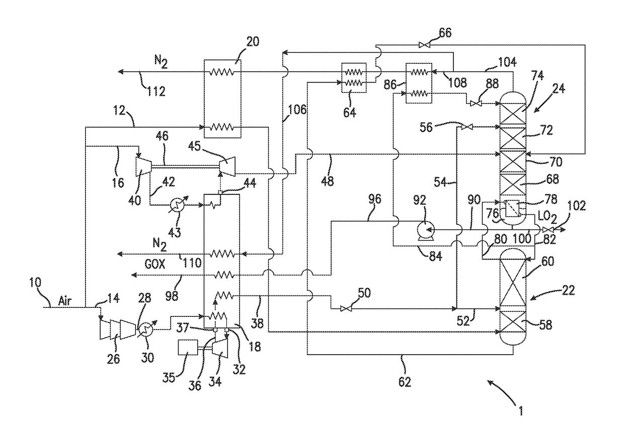
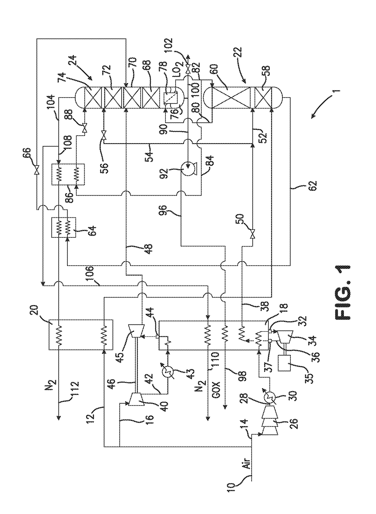
[0034]With reference to the FIG. 1, an air separation plant 1 is illustrated that is designed to produce an oxygen product stream 98 at pressure. In air separation plant 1, a compressed and purified air stream 10 is divided into a first compressed stream 12, a second compressed stream 14 and a third compressed stream 16. Although not illustrated, compressed and purified air stream 10 can originate from a main air compressor that compresses the air to a pressure of between 4.5 and 7.0 bar(a) and then purified of higher boiling contaminants by means of an adsorption bed system having known adsorbent beds operating in an out-of-phase cycle, typically, a temperature swing cycle. Such higher boiling contaminants are those that would solidify or concentrate at cryogenic temperatures; for instance, carbon dioxide, water vapor and hydrocarbons. The air separation plant 1 could be part of an enclave of such plants or similar plants; and therefore, the compressed and purified air stream 10 co...


PUM


Abstract

A method and apparatus for separating air in which an oxygen-rich liquid stream is pumped and then heated within a heat exchanger to produce an oxygen product through indirect heat exchange with first and second boosted pressure air streams. The first boosted pressure air stream is cold compressed at an intermediate temperature of the heat exchanger, reintroduced into the heat exchanger at a warmer temperature and then fully cooled and liquefied. The second boosted pressure air stream, after having been partially cooled, is expanded to produce an exhaust stream that is in turn introduced into a lower pressure column producing the oxygen-rich liquid. The second boosted pressure air stream is partially cooled to a temperature no greater than the intermediate temperature at which the cold compression occurs so that both the first and second boosted pressure air streams are able to take part in the heating of the oxygen-rich stream.

Description

FIELD OF THE INVENTION[0001]The present invention relates to a method and apparatus for separating air in which an oxygen-rich liquid stream produced by a distillation column arrangement is pressurized by pumping and then vaporized to produce an oxygen product as a vapor. More particularly, the present invention relates to such a method and apparatus in which the oxygen-rich liquid stream is heated through indirect heat exchange with an air stream that is subjected to cold compression at an intermediate temperature and another air stream that is partially cooled and expanded in a turboexpander that exhausts into the lower pressure column of the distillation column arrangement in order to impart refrigeration.BACKGROUND OF THE INVENTION[0002]Air is separated to produce oxygen, nitrogen and argon-rich products through the cryogenic rectification of the air. Such cryogenic rectification is conducted by compressing the air, purifying the air of higher boiling contaminants such as water ...

Claims


Application Information

Patent Timeline
Patent Type & Authority Applications(United States)
IPC IPC(8): F25J3/04F25J3/08
CPCF25J3/04412F25J2240/44F25J2240/10F25J2230/40F25J2230/24F25J3/04678F25J3/04387F25J3/04303F25J3/04218F25J3/04133F25J3/0409F25J3/04084F25J3/04054F25J3/04957F25J3/04781F25J3/08F25J3/04648F25J3/04109F25J3/04642F25J2245/58
Inventor PROSSER, NEIL M.
Owner PRAXAIR TECH INC
Why Eureka
Try Eureka