Method and apparatus for guiding a nonwoven web

a nonwoven web and guide device technology, applied in the field of nonwoven web handling, can solve the problems of poor operation performance, tearing or undesired wrinkles in the nonwoven web, and the adverse effect of operation performance, so as to reduce the disturbing influence of air currents, reduce the thickness, and reduce the effect of grammag

Active Publication Date: 2018-10-09
REIFENHAUSER GMBH & CO MASCHFAB
View PDF12 Cites 1 Cited by
  • Summary
  • Abstract
  • Description
  • Claims
  • Application Information

AI Technical Summary

Benefits of technology

[0005]It is therefore an object of the present invention to provide an improved method for guiding a nonwoven web.
[0006]Another object is the provision of such an improved method for guiding a nonwoven web that overcomes the above-given disadvantages, in particular with which the disadvantages described above can be effectively avoided.
[0024]A second embodiment of the invention that comprises the treatment roller assembly is characterized in that a stabilization plate is provided above the nonwoven web and another stabilization plate is provided below the nonwoven web spacedly or immediately upstream of the treatment roller assembly in the travel direction of the nonwoven web. The traveling nonwoven web is then at least partially guided through a clearance gap between the stabilization plate provided below the nonwoven web and the stabilization plate positioned above the nonwoven web. It is within the scope of the invention that in these embodiments, the ends of the stabilization plates are aligned or are substantially aligned in the vertical direction. However, the stabilization plates can be slightly displaced or offset. The stabilization plates provided above and below the nonwoven web make it possible to reduce or, in some regions where there is no interference, divert the flow of air caused by movement of the nonwoven web.
[0025]According to one embodiment of the invention, one stabilization plate has a plurality of grooves at a face thereof turned toward the nonwoven web, and the grooves may be at least partially aligned parallel to one another according to one embodiment. The grooves may also be provided, for example, in a herringbone pattern. These grooves provided in the face of the stabilization plate make it possible to reduce the frictional forces between the moving nonwoven web and the preferably non-moving stabilization plate. The grooves make it possible to divert away air currents or air layers resulting from the movement of the nonwoven web. One embodiment of the invention is characterized in that openings or pressure equalization openings are provided in a stabilization plate. These openings or pressure equalization openings may be positioned near or in the grooves. It is possible for air to be suctioned out of the intermediate region between the nonwoven web and the stabilization plate via the pressure equalization openings. It is within the scope of the invention that the air currents between nonwoven web and stabilization plate can be adjusted or influenced in an advantageous manner through the number and arrangement of the grooves and / or through the number and arrangement of the pressure equalization openings.
[0036]The invention is based on the discovery that with the method according to the invention or the nonwoven-web guide assembly according to the invention, nonwoven webs can be guided in an optimal, functionally reliable, and disturbance-free manner, and indeed even nonwoven webs that have a small thickness and low grammage can be thus guided. The disturbing influence of air currents can be greatly reduced or minimized with the aid of the guidance means according to the invention, such that an undesired fluttering of the nonwoven web no longer occurs or occurs only negligibly. Overall, the operational performance of the moving nonwoven web can be remarkably improved as compared to many known methods and guide assemblies. Undesirably high web tension is not needed, such that any undesired reductions in the nonwoven web width and undesired reductions in the strength of the nonwoven web in the transverse direction, which would result therefrom, will also not occur. It should be emphasized that the object according to the invention can be attained with relatively simple and inexpensive measures, and indeed surprisingly effectively and functionally reliably so.

Problems solved by technology

When a nonwoven web is conveyed with a deposition screen belt and / or by guide rollers and / or treatment rollers, a flow of air that moves in the travel direction of the nonwoven web is produced at all times. With respect to the nonwoven webs, this flow of air leads to a poor operational performance, especially in the region of the guide rollers and / or treatment rollers between the deposition screen belt and a windup device.
The operational performance is also adversely affected at the deposition screen belt and in the region of the winder.
The poor operational performance results in a fluttering of the nonwoven web that may result in tearing or undesired wrinkling in the nonwoven web.
This higher web tension results in turn in a smaller width of the nonwoven web on the winder, as well as deteriorated properties of the nonwoven web, especially a lower resistance or tensile strength of the nonwoven web transversely to the machine direction (in the CD direction).
The air entrained by the nonwoven web can also be problematic when the nonwoven web travels around a guide roller and / or a treatment roller.
This can lead to an undesired floating of the nonwoven web on the roller; in addition, a flow of air may be directed out from a roller onto the nonwoven web face, causing the product to have undesired non-homogeneous properties.
These measures not only are complex and expensive, but also have often failed to produce the desired results.
Here, too, satisfactory results have generally not been achieved thus far.

Method used


Image

  • Method and apparatus for guiding a nonwoven web
  • Method and apparatus for guiding a nonwoven web
  • Method and apparatus for guiding a nonwoven web

Examples


Embodiment Construction

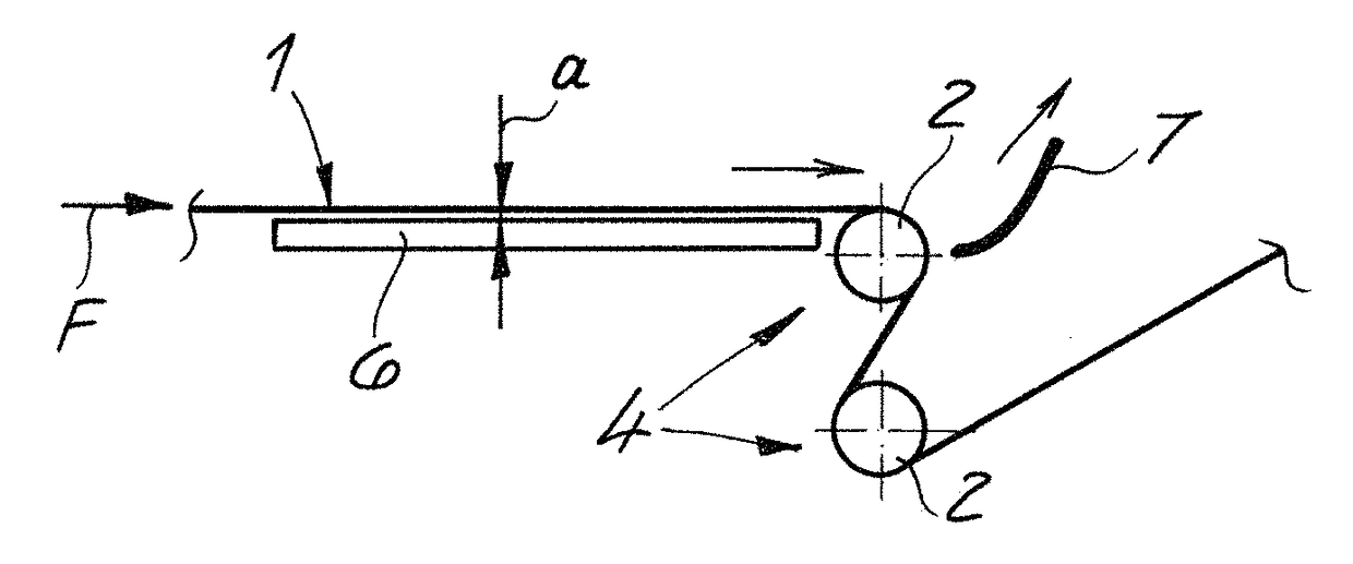
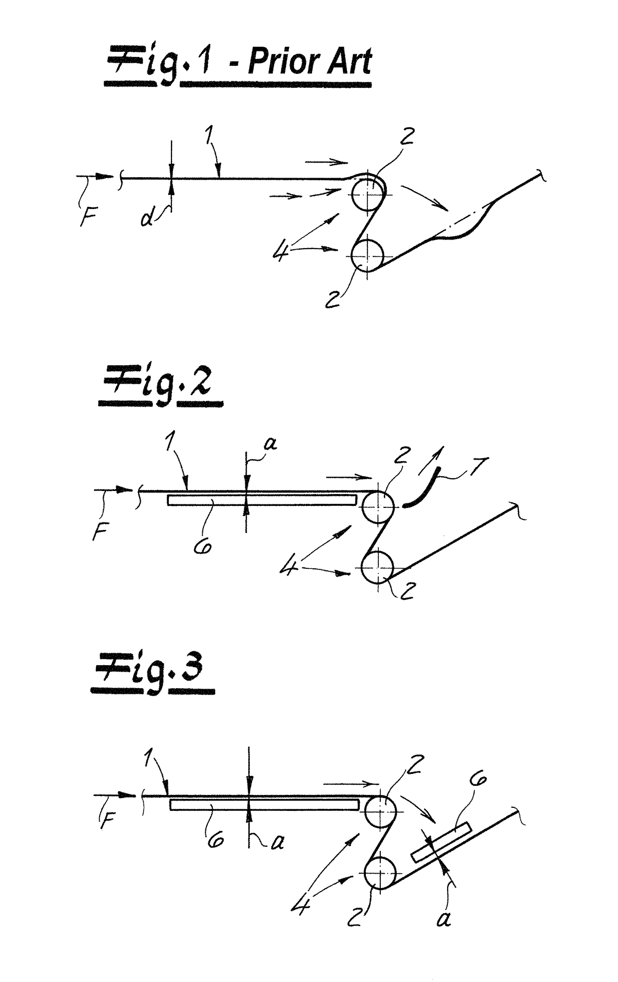
[0046]As seen in FIG. 1 a prior-art nonwoven-web guide assembly according to the invention carries out a method according to the invention of guiding a nonwoven web 1 made of plastic fibers conveyed in a travel direction F. The plastic fibers—preferably and in the embodiment—are continuous plastic filaments advantageously composed of a thermoplastic. Such a web is typically made by depositing the filaments forming the web on an upper reach of a horizontally extending foraminous web through which air is drawn downward. The deposited filaments are compressed into the coherent web 1.

[0047]In the embodiment according to the drawings, the nonwoven web 1 may be a spunbond nonwoven web. In particular, it is within the scope of the invention to use a nonwoven web laminate as the nonwoven web, where the laminate preferably comprises at least one spunbond nonwoven web and one melt-blown nonwoven web; particularly preferably is a laminate having a layering sequence of spunbond nonwoven web / mel...


PUM

PropertyMeasurementUnit
thicknessaaaaaaaaaa
travel speedaaaaaaaaaa
lengthaaaaaaaaaa

Abstract

A nonwoven web made of plastic fibers and having a web thickness less than 2 mm (preferably less than 1.5 mm) and a grammage less than 30 g / m2 (preferably less than 25 g / m2) and conveyed this web in a travel direction so that it physically contacts a guide or treatment roller. A stabilization plate extending in and transversely to the travel direction of the nonwoven web is provided upstream or downstream of the roller in the travel direction, and the nonwoven web is guided in the travel direction past the stabilization plate such that a spacing between a face of the stabilization plate turned toward the nonwoven web and the nonwoven web face is 0 to 20 mm (preferably 0.1 to 10 mm, and very preferably 0.2 to 5 mm).

Description

FIELD OF THE INVENTION[0001]The present invention relates to the handling of a nonwoven web during its manufacture and use. More particularly this invention concerns a method and apparatus for guiding a nonwoven web made of plastic fibers.BACKGROUND OF THE INVENTION[0002]During manufacture, a nonwoven web is generally guided via guide and / or treatment rollers after the plastic fibers have been deposited to form the nonwoven web. The treatment rollers may be, for example, pinch rollers for compacting the nonwoven web or calender rollers for calendering the nonwoven web.[0003]A method and apparatus of the above-described type is known in various embodiments from the prior art. When a nonwoven web is conveyed with a deposition screen belt and / or by guide rollers and / or treatment rollers, a flow of air that moves in the travel direction of the nonwoven web is produced at all times. With respect to the nonwoven webs, this flow of air leads to a poor operational performance, especially in...

Claims


Application Information

Patent Timeline
Patent Type & Authority Patents(United States)
IPC IPC(8): D06C29/00D04H1/44D04H3/14D04H3/02D06C15/02D06C15/08
CPCD06C29/00D04H1/44D06C15/08D04H3/14D06C15/02D04H3/02B65H23/26B65H23/28B65H2404/00D01D5/12D04H3/033
Inventor HOFEMEISTER, HANS-JUERGENGEUS, HANS-GEORGGORETZKI, FELIXKLEIN, ALEXANDERNITSCHKE, MICHAELFREY, DETLEFNEUENHOFER, MARTIN
Owner REIFENHAUSER GMBH & CO MASCHFAB
Why Eureka
Try Eureka