Burner

a burner and burner technology, applied in the field of burners, can solve the problems of increasing the number of components, increasing the cost and weight of the engine, and increasing the unreliability of the engin

Active Publication Date: 2021-12-21
ROLLS ROYCE PLC
View PDF16 Cites 0 Cited by
  • Summary
  • Abstract
  • Description
  • Claims
  • Application Information

AI Technical Summary

Benefits of technology

[0009]When the air pressure in the vicinity of the at least one diverting passage is not reduced via the control duct(s), air flows substantially equally in the inner and outer air flow passages. When the air pressure in the vicinity of the at least one diverting passage is reduced via the control duct(s), air flow is diverted to the outer air flow passage (through the at least one diverting passage) such that the air flow in the inner air flow passage is reduced (or even eliminated).
[0049]This allows the air pressure reduction effected via the control duct(s) to be varied around the circumference of the annular chamber, the method resulting in a greater air pressure reduction (and therefore greater diversion of inner air flow to the outer air flow passage) being possible in the areas having reduced spacing and / or greater density.

Problems solved by technology

The control valves (and the plurality of fuel ducts) create complexity in the gas turbine engine and increase the number of component parts which in turn increases unreliability, cost and weight of the engine.

Method used


Image

  • Burner
  • Burner
  • Burner

Examples


Embodiment Construction

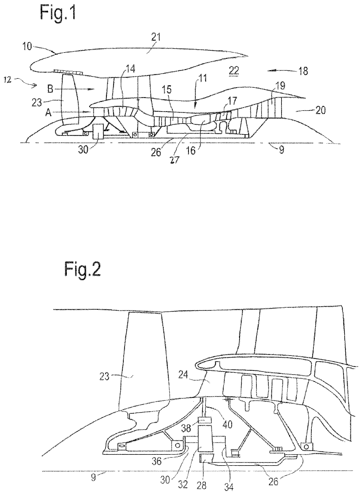
[0067]The present disclosure concerns a burner for a gas turbine engine. Such a gas turbine engine may comprise an engine core comprising a turbine, a combustor, a compressor, and a core shaft connecting the turbine to the compressor. Such a gas turbine engine may comprise a fan (having fan blades) located upstream of the engine core.

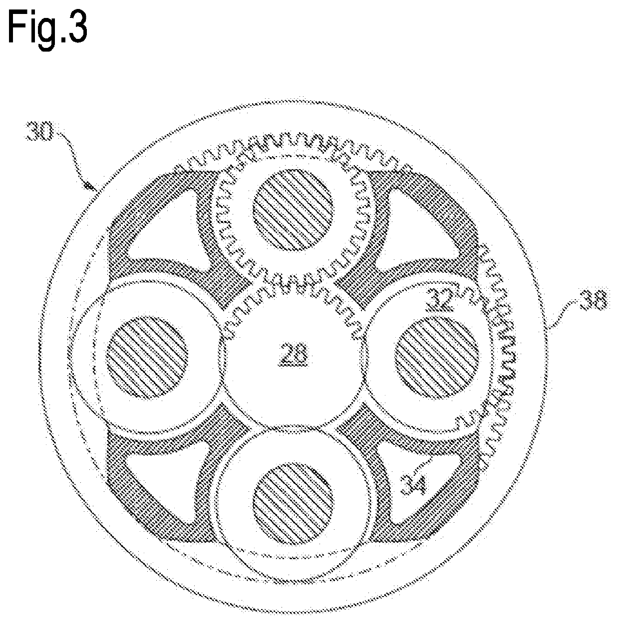
[0068]Arrangements of the present disclosure may be particularly, although not exclusively, beneficial for fans that are driven via a gearbox. Accordingly, the gas turbine engine may comprise a gearbox that receives an input from the core shaft and outputs drive to the fan so as to drive the fan at a lower rotational speed than the core shaft. The input to the gearbox may be directly from the core shaft, or indirectly from the core shaft, for example via a spur shaft and / or gear. The core shaft may rigidly connect the turbine and the compressor, such that the turbine and compressor rotate at the same speed (with the fan rotating at a lower speed).

[0069]...


PUM


Abstract

There is provided a burner for a gas turbine engine, the burner comprising a radially inner pilot fuel flow passage surrounded by a radially outer main fuel flow passage. The main fuel flow passage is interposed between concentrically arranged radially inner and radially outer air flow passages. The inner and outer air flow passages are in fluid communication with one another via at least one diverting passage at an upstream end of the burner. The burner further comprises at least one control duct connectable to a reduced pressure / vacuum source for selectively reducing the air pressure in the vicinity of the diverting passage such that air flow is selectively diverted from the inner air flow passage to the outer flow passage via the diverting passage.

Description

CROSS-REFERENCE TO RELATED APPLICATIONS[0001]This application is based upon and claims the benefit of priority from United Kingdom patent application Number GB 1808070.5 filed on May 18, 2018, the entire contents of which are incorporated herein by reference.BACKGROUNDTechnical Field[0002]The present disclosure relates to a burner for a combustion system e.g. for a lean-burn combustion system within a gas turbine engine. The present disclosure also relates to a combustion system having a burner, to a gas turbine engine having a combustion system and to a method of controlling the combustion cycle of a gas turbine engine.Description of the Related Art[0003]The combustion system of a gas turbine engine typically comprises a plurality of burners which mix fuel and air flows to generate (after ignition within a combustion chamber) a pilot flame and a main flame, the pilot flame facilitating continuity of ignition of the main flame.[0004]Lean-burn combustion systems typically direct a gr...

Claims


Application Information

Patent Timeline
Patent Type & Authority Patents(United States)
IPC IPC(8): F23R3/00F23R3/26F23C7/00F23R3/14
CPCF23R3/26F23C7/006F23R3/14F23R3/02F23R3/04F23R3/343F23D11/408
Inventor BELLIS, MARK JE
Owner ROLLS ROYCE PLC
Why Eureka
Try Eureka