Imaging optical system

a technology of optical system and optical system, applied in the field of imaging optical system, can solve the problems of insufficient aberration of compact large size and weight of wide-angle imaging optical system, and relatively difficult manufacturing process

Pending Publication Date: 2022-10-13
IKEMORI KEIJI +1
View PDF0 Cites 1 Cited by
  • Summary
  • Abstract
  • Description
  • Claims
  • Application Information

AI Technical Summary

Benefits of technology

[0013]The imaging optical system according to the present embodiment is configured such that the bundle of rays that enters the imaging optical system and reaches the maximum value of image height and the bundle of rays that enters the imaging optical system and has the principal ray parallel to the optical axis do not intersect with each other within the first lens from the object side and within the lens closest to the image. When an aspheric lens in which radius of curvature of each of both surfaces is infinity in the paraxial region and which has a power of the third-order aberration region in the peripheral area is used as each of the first lens and / or the second lens from the object side and the lens closest to the image in the layout described above, a compact wide-angle imaging optical system with sufficiently small aberrations can be realized. Further, in particular, off-axis aberrations can be effectively reduced by locating at least one aspheric lens in which radius of curvature of each of both surfaces is infinity in the paraxial region and which has a power of the third-order aberration region in the peripheral area respectively on the object side and on the image side of the aperture stop.
[0029]According to the present embodiment, a compact wide-angle imaging optical system with sufficiently small aberrations can be realized by locating an aspheric lens in which radius of curvature of each of both surfaces is infinity in the paraxial region and which has a power of the third-order aberration region in the peripheral area in a position where the off-axis bundle of rays and the axial bundle of rays do not intersect with each other instead of a lens that has a great power in the paraxial region.
[0031]According to the present embodiment, a compact wide-angle imaging optical system with sufficiently small aberrations can be realized by locating an aspheric lens in which radius of curvature of each of both surfaces is infinity in the paraxial region and which has a power of the third-order aberration region in the peripheral area in a position where the off-axis bundle of rays and the axial bundle of rays do not intersect with each other instead of a lens that has a great power in the paraxial region.

Problems solved by technology

The use of lenses each of which has a great power in the paraxial region makes the manufacturing process relatively difficult because of a required higher accuracy of assembling and further makes the size and the weight of the wide-angle imaging optical system greater.
However, a compact wide-angle imaging optical system with sufficiently small aberrations has not been realized.Patent document 1: JP2020-201382APatent document 2: JP2021-001938APatent document 3: JP2021-018291APatent document 4: JP2021-021900A

Method used


Image

  • Imaging optical system
  • Imaging optical system
  • Imaging optical system

Examples


example 1

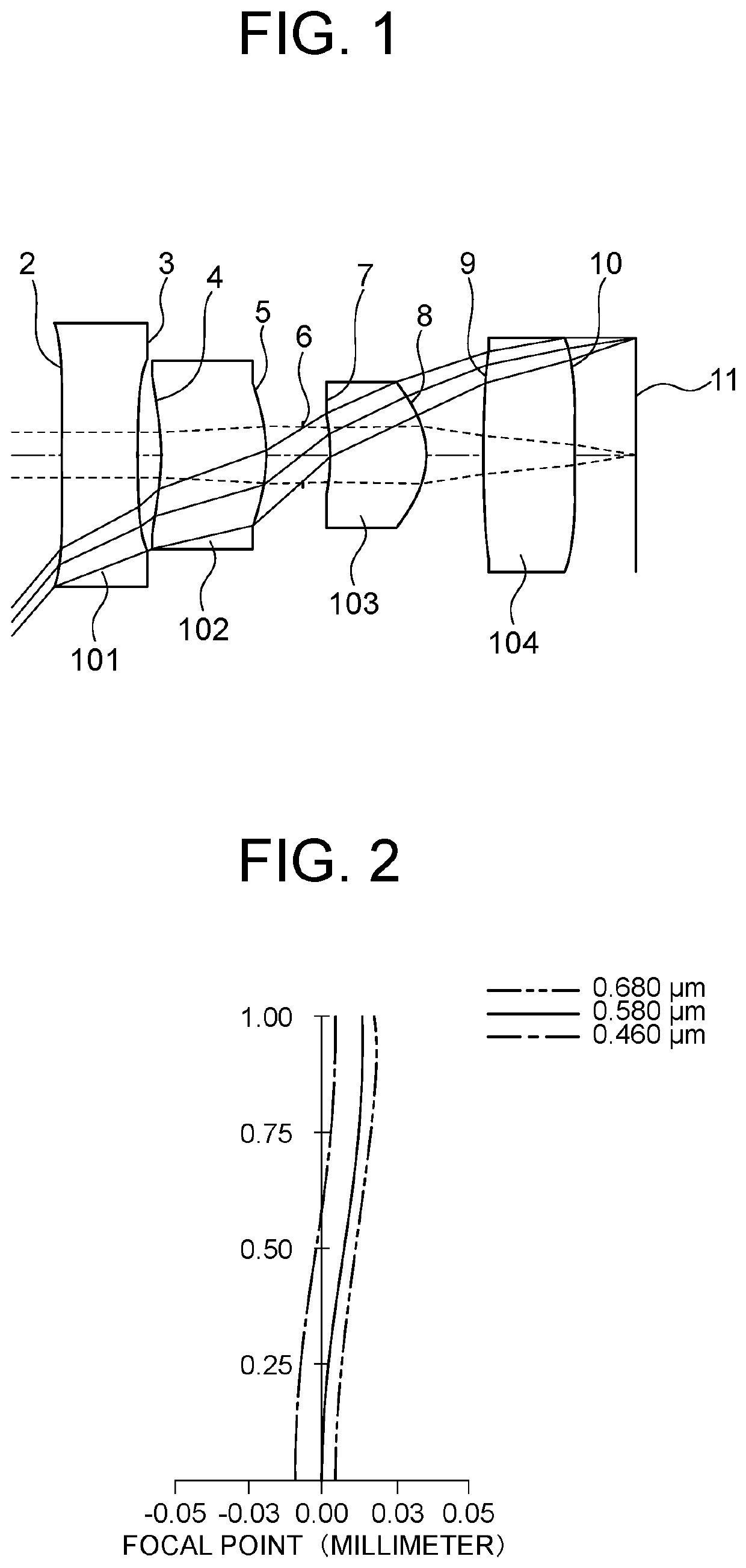
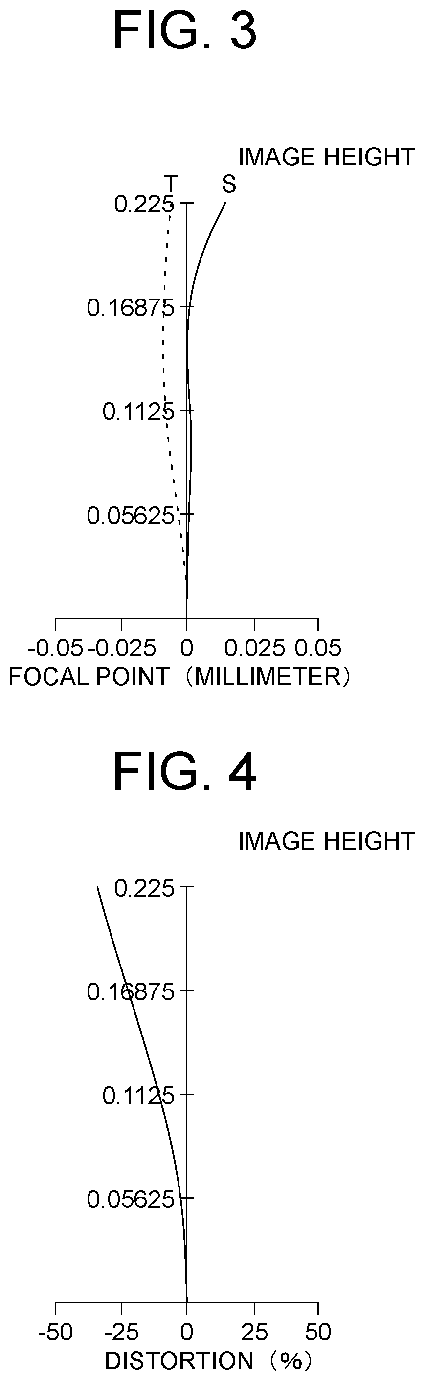
[0158]FIG. 1 shows a layout of an imaging optical system of Example 1. The imaging optical system includes four lenses arranged from the object side to the image side. Each of the first lens 101 and the fourth lens 104 is an aspheric lens in which radius of curvature of each of both surfaces is infinity in the paraxial region and which has a power in the peripheral area. Each of the second lens 102 and the third lens 103 is a positive meniscus lens which is convex toward the image. The aperture stop 6 is located between the second lens 102 and the third lens 103.

[0159]Table 1 shows positions of the optical elements and properties and values of focal length of the lenses of the imaging optical system of Example 1. The focal length f of the whole imaging optical system is given by f=0.2808. The F-number Fno is given by Fno=3.348. HFOV representing a half value of angle of view is given by HFOV=50 (degrees). In Table 1, each of the four lenses is represented respectively by lens 1 to l...

example 2

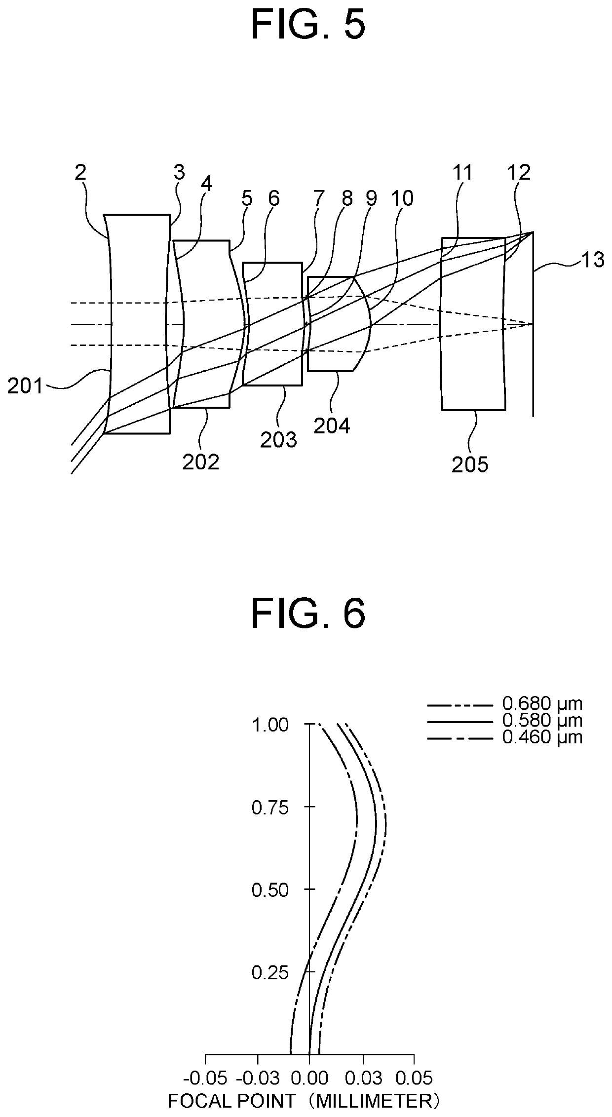
[0165]FIG. 5 shows a layout of an imaging optical system of Example 2. The imaging optical system includes five lenses arranged from the object side to the image side. Each of the first lens 201 and the fifth lens 205 is an aspheric lens in which radius of curvature of each of both surfaces is infinity in the paraxial region and which has a power in the peripheral area. Each of the second lens 202 and the fourth lens 204 is a positive meniscus lens which is convex toward the image. The third lens 203 is a negative meniscus lens which is convex toward the image. The aperture stop 8 is located between the third lens 203 and the fourth lens 204.

[0166]Table 3 shows positions of the optical elements and properties and values of focal length of the lenses of the imaging optical system of Example 2. The focal length f of the whole imaging optical system is given by f=0.264. The F-number Fno is given by Fno=2.563. HFOV representing a half value of angle of view is given by HFOV=50 (degrees)...

example 3

[0172]FIG. 9 shows a layout of an imaging optical system of Example 3. The imaging optical system includes five lenses arranged from the object side to the image side. Each of the second 302 and the fifth lens 305 is an aspheric lens in which radius of curvature of each of both surfaces is infinity in the paraxial region and which has a power in the peripheral area. The first lens 301 is a biconcave lens. The third lens 303 is a biconvex lens. The fourth lens 304 is a positive meniscus lens which is convex toward the image. The aperture stop 8 is located between the third lens 303 and the fourth lens 304.

[0173]Table 5 shows positions of the optical elements and properties and values of focal length of the lenses of the imaging optical system of Example 3. The focal length f of the whole imaging optical system is given by f=0.206. The F-number Fno is given by Fno=2.5814. HFOV representing a half value of angle of view is given by HFOV=50 (degrees). In Table 5, each of the five lenses...


PUM


Abstract

An imaging optical system wherein the number of lenses is three to seven, one to four lenses, each of which is an aspheric lens in which radius of curvature of each of both surfaces is infinity in the paraxial region and which has a power of the third-order aberration region in the peripheral area are provided, the first lens from the object side is a negative lens or the aspheric lens, the relationship0.1⁢8<(∑i=1i=n<semantics definitionURL="">❘<annotation encoding="Mathematica">"\[LeftBracketingBar]"< / annotation>< / semantics>1fi<semantics definitionURL="">❘<annotation encoding="Mathematica">"\[RightBracketingBar]"< / annotation>< / semantics>)·fn<0.9is satisfied where i represents a natural number, fi represents focal length of the i-th lens from the object side, f represents focal length of the whole system and n represents the number of the lenses, and the relationship40°<HFOV<80°is satisfied where HFOV represents angle that the principal ray of bundle of rays that enters the imaging optical system and reaches the maximum value of image height forms with the optical axis.

Description

TECHNICAL FIELD[0001]The present invention relates to an imaging optical system, particular to a wide-angle imaging optical system.BACKGROUND ART[0002]In a wide-angle imaging optical system using spherical lenses, lenses each of which has a great power in the paraxial region are used to reduce aberrations. Similarly in a wide-angle imaging optical system using aspheric lenses, many lenses each of which has a great power in the paraxial region are used.[0003]The use of lenses each of which has a great power in the paraxial region makes the manufacturing process relatively difficult because of a required higher accuracy of assembling and further makes the size and the weight of the wide-angle imaging optical system greater.[0004]Imaging optical systems each of which includes an aspheric lens in which radius of curvature of each of both surfaces is infinity in the paraxial region have been developed (for example patent documents 1 to 4). However, a compact wide-angle imaging optical sy...

Claims


Application Information

Patent Timeline
Patent Type & Authority Applications(United States)
IPC IPC(8): G02B13/00G02B9/34G02B9/60G02B9/62G02B9/64
CPCG02B13/002G02B9/34G02B9/60G02B9/62G02B9/64G02B13/06G02B13/18
Inventor IKEMORI, KEIJISHIH-YUAN, CHANGZENKO, TETSUYAISHII, KENTASEKI, DAISUKE
Owner IKEMORI KEIJI
Why Eureka
Try Eureka