Supercharge Your Innovation With Domain-Expert AI Agents!

Door locking mechanism for a sterilizer

Pending Publication Date: 2022-10-27
SAJKAN LTD
View PDF5 Cites 0 Cited by
  • Summary
  • Abstract
  • Description
  • Claims
  • Application Information

AI Technical Summary

Benefits of technology

The present invention provides a door locking mechanism for a sterilizer that includes a locking arm, a sensor arm, a motor, a cam, and a closing switch. The locking arm is connected to the frame of the sterilizer and can move between a locked position and an unlocked position. The sensor arm is flexible and can be displaced by pressure from the extendible portion of the door as it passes through the cutaway portion. The locking arm has a cutaway portion that allows the extendible portion of the door to pass through. The closing switch detects displacement of the sensor arm and signals to the operating system of the sterilizer that the door is in a latched position. The locking switch detects movement of the locking arm and signals to the operating system that the door is in the locked position. The mechanism ensures secure locking of the door and prevents unauthorized access to the sterilizer.

Problems solved by technology

Sterilizer door locking mechanisms can face multiple issues during operation, such as jamming while in the closed and locked position.
This often occurs due to the high forces the pressure and temperature places on the locking mechanism, which increases friction forces that exceed what the door-actuating device can handle.

Method used


Image

  • Door locking mechanism for a sterilizer
  • Door locking mechanism for a sterilizer
  • Door locking mechanism for a sterilizer

Examples


Embodiment Construction

[0042]The following detailed description of the preferred embodiment(s) is merely exemplary in nature and is in no way intended to limit the invention, its application, or uses. While but a single embodiment of the present invention has generally been herein shown and described, it will be understood that various changes may be made without departing from the scope of the invention.

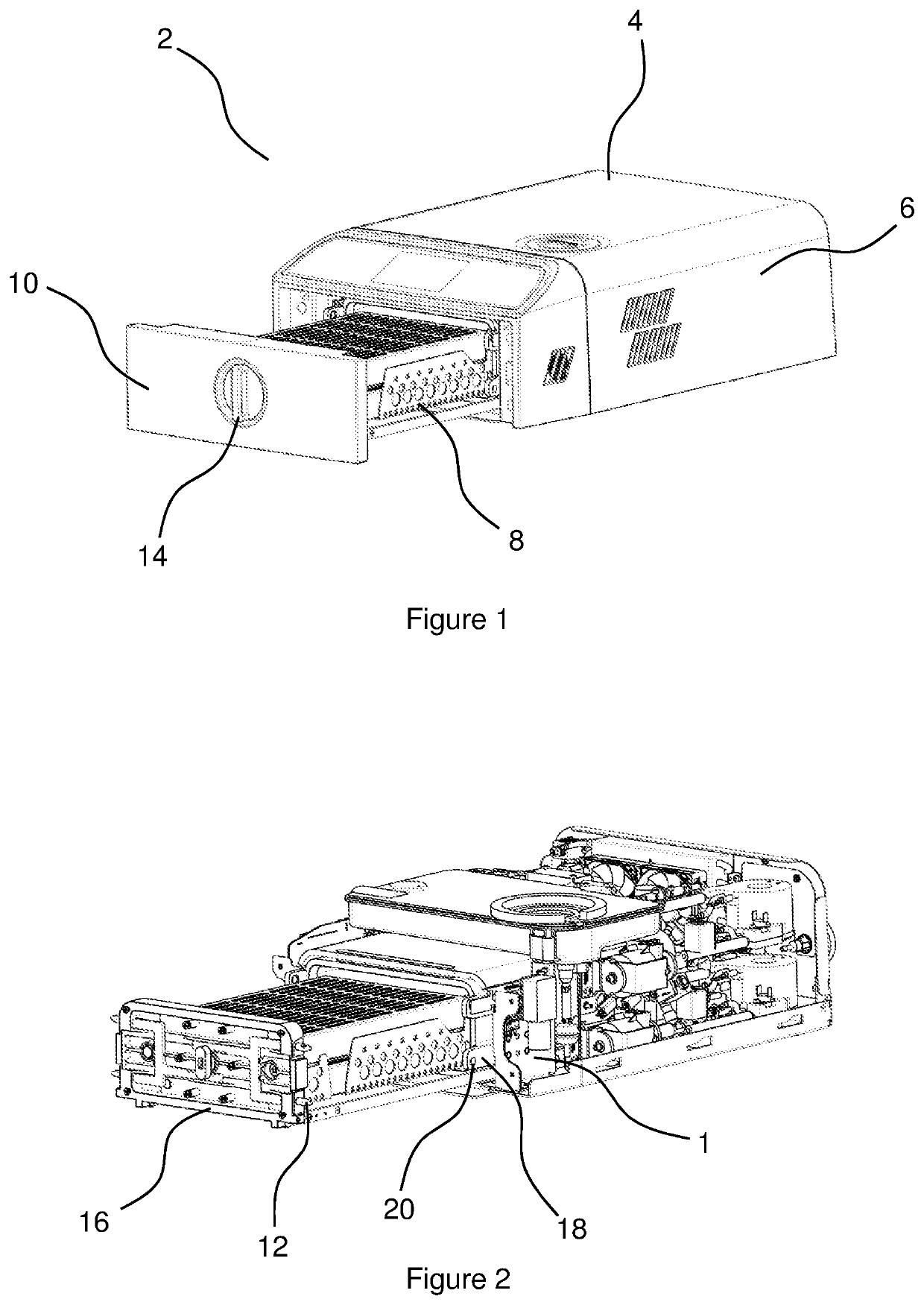
[0043]FIG. 1 illustrates a known benchtop sterilizer 2, having a main body 4 that includes the interior sterilizing chamber and the necessary components to operate the sterilizer 2, and an outer casing 6. A drawer 8 can be used for inserting articles into the interior sterilizing chamber. In this version of the sterilizer 2, a door 10 is attached to the front of the drawer 8 and closes when the drawer 8 is fully entered into the chamber. Alternative versions of sterilizers 2 may have a door hingedly attached that swings between open and closed positions.

[0044]In FIG. 2, the casing 6 of the entire steriliz...


PUM


Abstract

A door locking mechanism for a sterilizer that minimizes the occurrence of jamming during operation, and that can be manually actuated if necessary. The door locking mechanism abuts the door of the sterilizer, and comprises a locking arm hingedly connected to a frame to permit the locking arm to move between a locked position and an unlocked position, the locking arm having a cutaway portion, the cutaway portion permitting an extendible portion of the door to extend therethrough; a sensor arm arranged adjacent to the locking arm, the sensor arm being flexible to permit the sensor arm to be at least partially displaced away from the locking arm in response to applied pressure to the sensor arm from the extendible portion of the door as it passes through the cutaway portion; a motor in communication with the operating system; a camshaft actuated by the motor; a cam attached to the camshaft, the cam being in contact with the locking arm to move the locking arm between the locked position and the unlocked position; a closing switch positioned within the locking mechanism to detect displacement of the sensor arm, the closing switch being in communication with an operating system of the sterilizer such that when the closing switch detects displacement of the sensor arm it signals to the operating system that the door is in a latched position; and a locking switch positioned within the locking mechanism to detect movement of the locking arm into the locked position, the locking switch being in communication with the operating system such that when the locking switch detects the movement of the locking arm into the locked position it signals to the operating system that the door is in the locked position.

Description

FIELD OF THE INVENTION[0001]The present invention relates to sterilizers, such as for medical and dental articles, and more particularly, for a door locking mechanism for the sterilizer.BACKGROUND OF THE INVENTION[0002]Sterilizers are widely used in places such as medical and dental offices, and research laboratories, to sterilize reusable articles. Based on space and cost constraints, sterilizers come in many sizes, including smaller benchtop sterilizers. Regardless, of size, sterilizers typically have a door that provides access to the interior sterilizer chamber to allow for placing and removing articles. The interior chamber becomes steam filled during operation, and a heater is typically located within the chamber for increasing the temperature and pressure to sterilize the articles. Some sterilizers include features that can perform a drying cycle prior to removal of the articles.[0003]During the sterilization cycle, temperature and pressure inside the chamber will reach high ...

Claims


Application Information

Patent Timeline
IPC IPC(8): A61L2/26E05B65/46
CPCA61L2/26E05B65/46A61L2202/121E05B2047/005E05C9/04E05B2047/0069E05B47/0012E05B47/0607E05B17/2034E05B2047/0067
Inventor GAL, STELIAN GABRIELNEAGOE, GABRIEL
Owner SAJKAN LTD
Features
  • R&D
  • Intellectual Property
  • Life Sciences
  • Materials
  • Tech Scout
  • Unparalleled Data Quality
  • Higher Quality Content
  • 60% Fewer Hallucinations
Learn More