Power storage module and method of manufacturing same

Pending Publication Date: 2022-10-27
PRIME PLANET ENERGY & SOLUTIONS INC
View PDF0 Cites 0 Cited by
  • Summary
  • Abstract
  • Description
  • Claims
  • Application Information

AI Technical Summary

Benefits of technology

[0006]An object of the present technology is to provide: a power storage module having high strength and allowi

Problems solved by technology

Further, stress concentration may be likely to occur due to dimensional precision of the restraint m

Method used


Image

  • Power storage module and method of manufacturing same
  • Power storage module and method of manufacturing same
  • Power storage module and method of manufacturing same

Examples


Example

[0031]Hereinafter, embodiments of the present technology will be described. It should be noted that the same or corresponding portions are denoted by the same reference characters, and may not be described repeatedly.

[0032]It should be noted that in the embodiments described below, when reference is made to number, amount, and the like, the scope of the present technology is not necessarily limited to the number, amount, and the like unless otherwise stated particularly. Further, in the embodiments described below, each component is not necessarily essential to the present technology unless otherwise stated particularly. Further, the present technology is not limited to one that necessarily exhibits all the functions and effects stated in the present embodiment.

[0033]It should be noted that in the present specification, the terms “comprise”, “include”, and “have” are open-end terms. That is, when a certain configuration is included, a configuration other than the foregoing configura...


PUM


Abstract

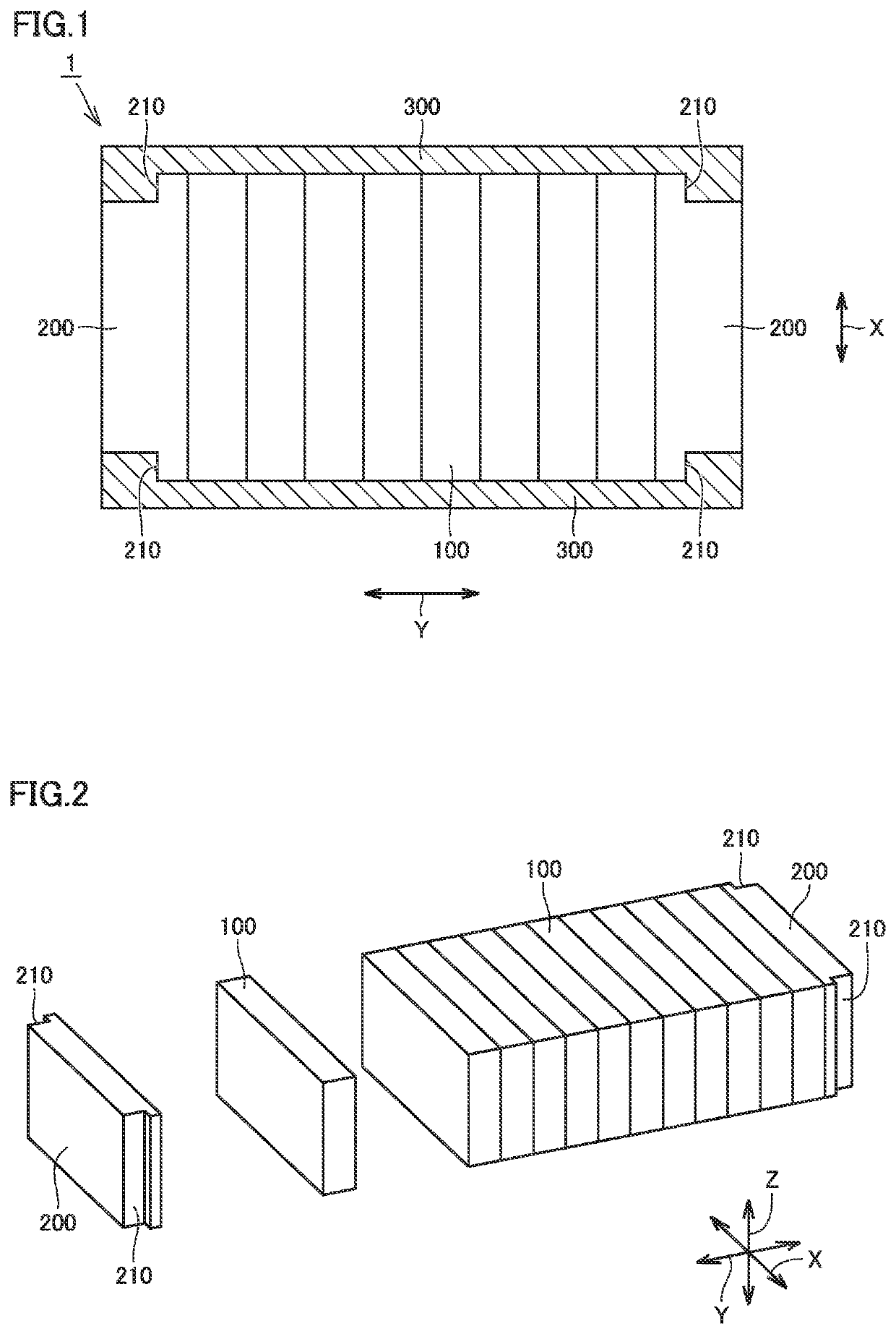
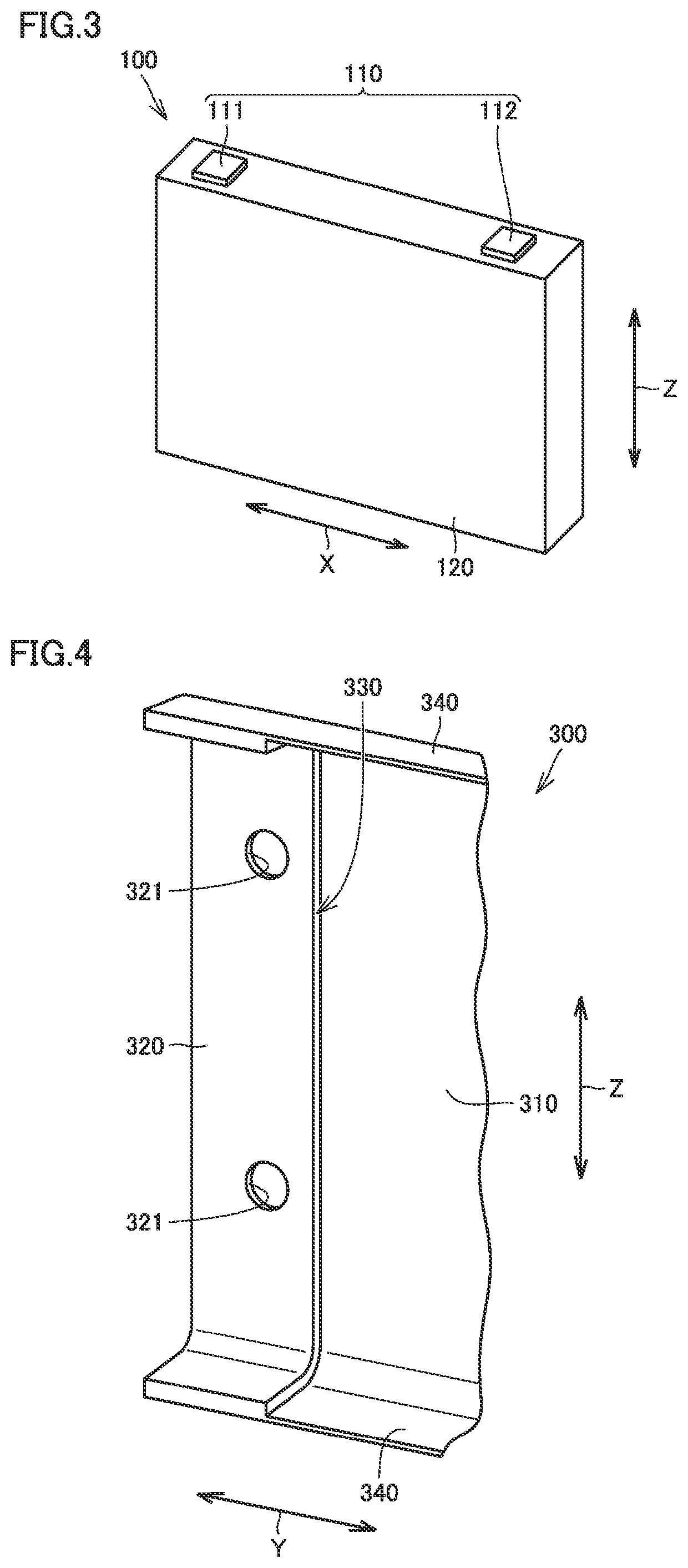
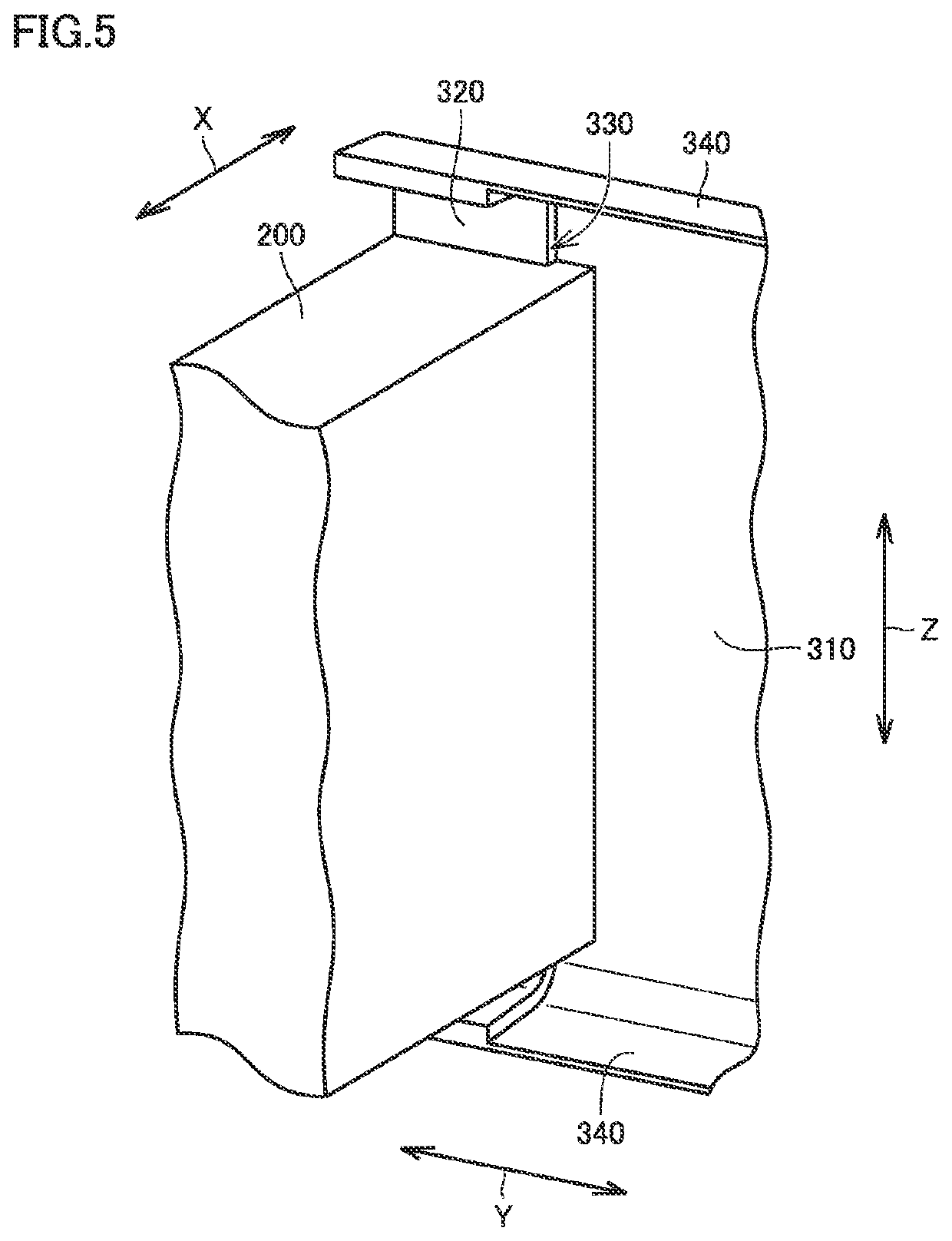
A power storage module includes: a plurality of power storage cells stacked along a first direction; an end plate provided at an end of a stack of the plurality of power storage cells; and a restraint member that restrains the end plate and the plurality of power storage cells in the first direction. The restraint member includes a thin portion, a thick portion, and a stepped surface between the thin portion and the thick portion, the thin portion and the thick portion being formed in one piece. The stepped surface is in abutment with the end plate in the first direction.

Description

[0001]This nonprovisional application is based on Japanese Patent Application No. 2021-071964 filed on Apr. 21, 2021, with the Japan Patent Office, the entire contents of which are hereby incorporated by reference.BACKGROUND OF THE INVENTIONField of the Invention[0002]The present technology relates to a power storage module and a method of manufacturing the power storage module.Description of the Background Art[0003]WO 2019 / 130936 discloses that in a restraint member that restrains a battery stack in an axial direction, a locking block to be brought into abutment with an end plate is spot-welded to a plate-shaped bar.[0004]When spot welding is used as in the structure described in WO 2019 / 130936, stress concentration may occur at the welded portion. Further, stress concentration may be likely to occur due to dimensional precision of the restraint member.[0005]It is required to increase the strength of the restraint member by employing a structure in which stress concentration is les...

Claims


Application Information

Patent Timeline
IPC IPC(8): H01M50/209H01M50/276
CPCH01M50/209H01M50/276H01M50/264H01M10/04Y02E60/10H01M10/0468H01M50/224
Inventor MOGI, YUYA
Owner PRIME PLANET ENERGY & SOLUTIONS INC
Why Eureka
Try Eureka