Effective component generation device and method for manufacturing same

a technology of component generation and component, which is applied in the direction of liquid supply arrangement, corona discharge, disinfection, etc., can solve the problems of insufficient reduction of electromagnetic noise to an outside of the case, leakage of electromagnetic noise, etc., and achieve the effect of reducing the influence of electromagnetic nois

Pending Publication Date: 2022-11-10
PANASONIC INTELLECTUAL PROPERTY MANAGEMENT CO LTD
View PDF0 Cites 0 Cited by
  • Summary
  • Abstract
  • Description
  • Claims
  • Application Information

AI Technical Summary

Benefits of technology

[0010]According to the present disclosure, it is possible to more effectivel

Problems solved by technology

Therefore, the electromagnetic noise leaks from the gap, and an influence of the

Method used


Image

  • Effective component generation device and method for manufacturing same
  • Effective component generation device and method for manufacturing same
  • Effective component generation device and method for manufacturing same

Examples


first exemplary embodiment

[0028]Hereinafter, effective component generation device 1 according to a first exemplary embodiment will be described in terms of items with reference to the drawings.

(1) Outline

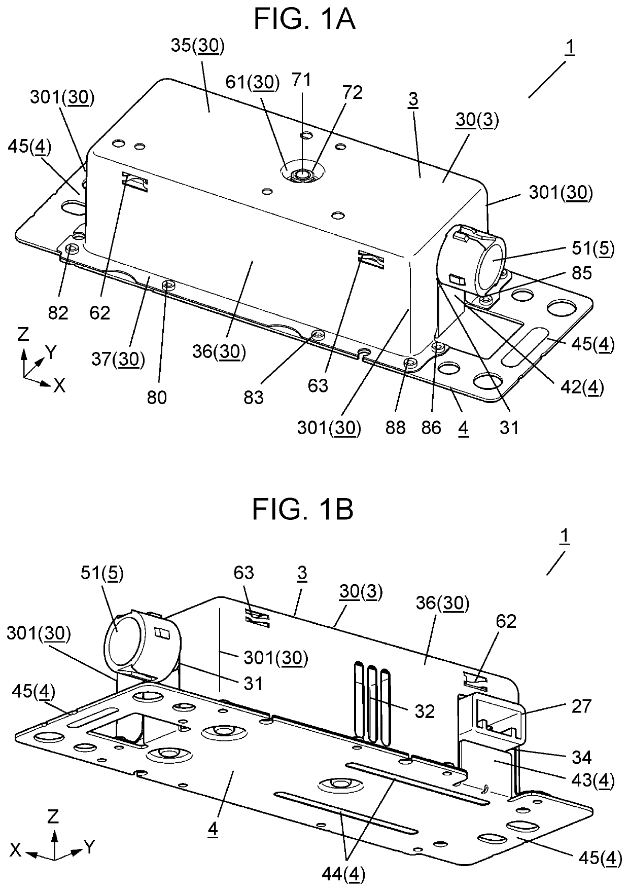
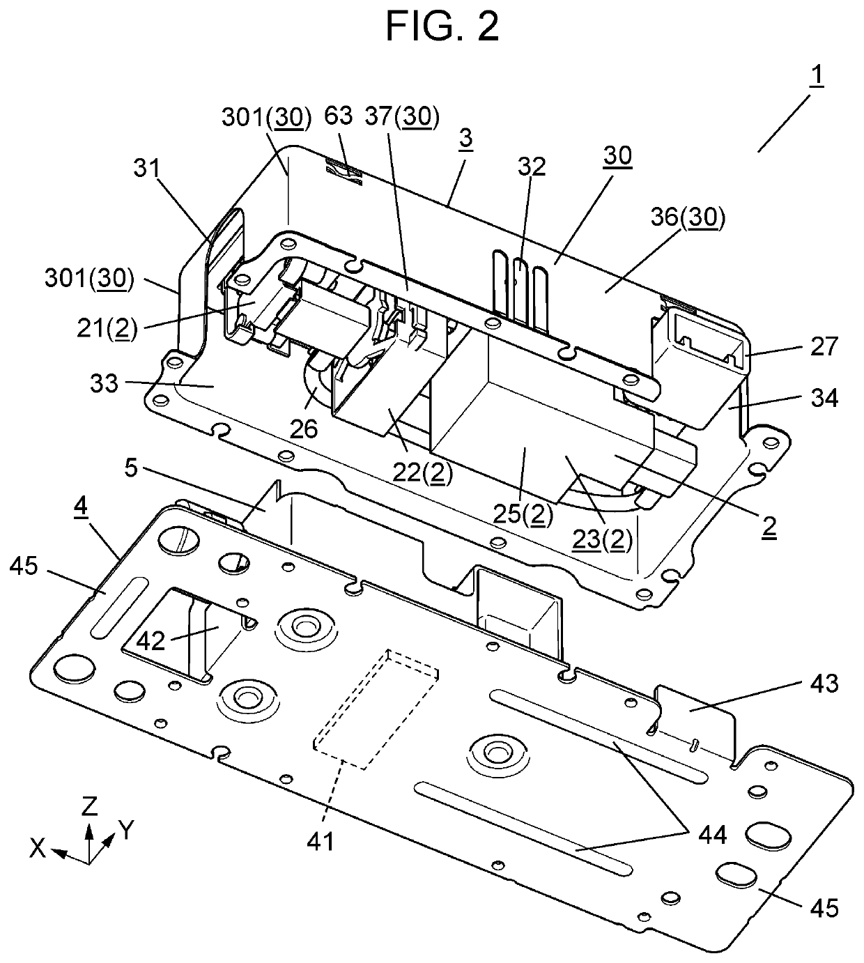
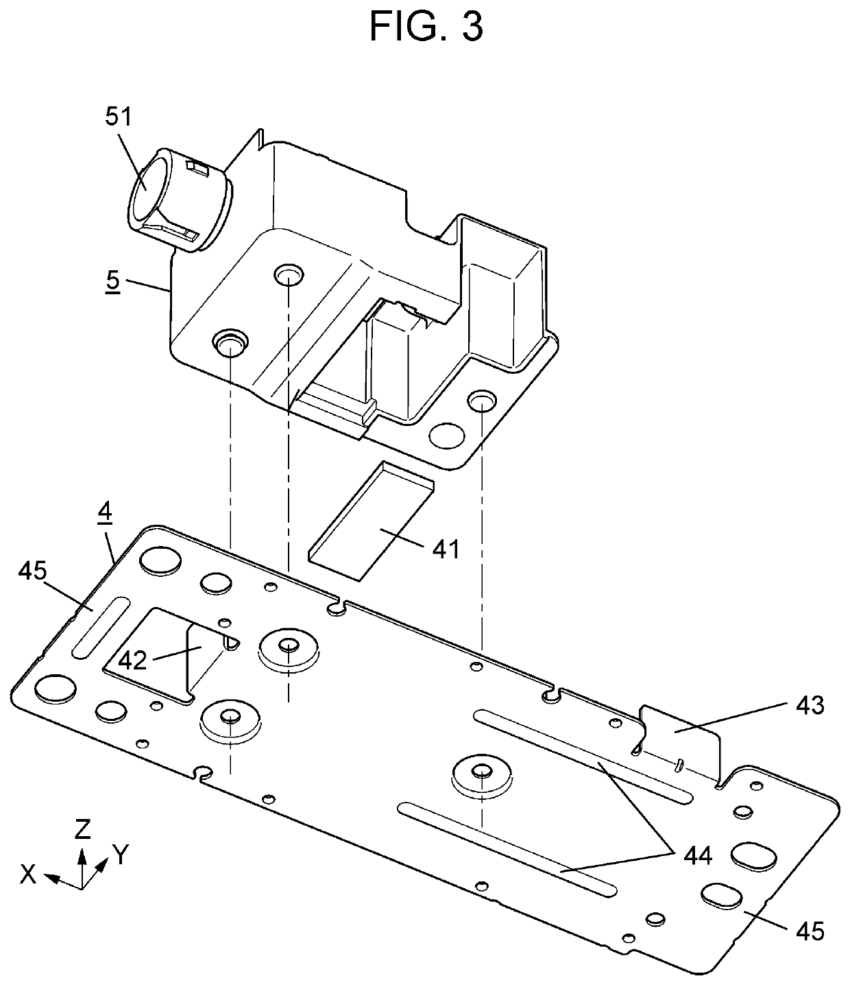
[0029]First, an outline of effective component generation device 1 according to the first exemplary embodiment will be described with reference to FIGS. 1A to 3.

[0030]Effective component generation device 1 includes discharger 21 (see FIG. 2) that generates an effective component. In the first exemplary embodiment, discharger 21 includes discharge electrode 211 (see FIG. 5), counter electrode 212 (see FIG. 5), and the like. When a voltage is applied between discharge electrode 211 and counter electrode 212, discharge is generated between the electrodes of discharger 21.

[0031]The “effective component” in the present disclosure is a component generated by the discharge of discharger 21. As an example, the effective component means a charged microparticle liquid containing OH radicals, OH radicals, O2 radicals...

second exemplary embodiment

[0175]Hereinafter, effective component generation device 1A according to a second exemplary embodiment will be described with reference to FIGS. 11A to 12B.

[0176]As illustrated in FIGS. 11A to 12B, effective component generation device 1A according to the second exemplary embodiment is different from effective component generation device 1 according to the first exemplary embodiment in that it includes shield wall 46. Hereinafter, common reference numerals denote the same constituent elements as those of the first exemplary embodiment, and descriptions of the constituent elements will be omitted as appropriate.

[0177]Shield wall 46 of effective component generation device 1A is provided on lid body 4, and is disposed in case 3 at a position overlapping discharger 21 when viewed from discharge port 31. In other words, shield wall 46 is disposed at a position between discharger 21 and discharge port 31 in plan view.

[0178]As illustrated in FIGS. 11B to 12B, shield wall 46 provided on li...


PUM


Abstract

Effective component generation device includes internal component and case. Internal components include discharger that generates an effective component. Case is formed in a box shape having discharge port through which an effective component is discharged, and houses internal components. Case includes metal body including a bottom plate and peripheral walls surrounding at least discharger in internal component. Metal body has seamless portion at a corner portion between two surfaces of adjacent peripheral walls oriented in different directions. As a result, there is provided effective component generation device capable of suppressing electromagnetic noise radiated to the outside of case and reducing an influence of electromagnetic noise to the outside.

Description

CROSS-REFERENCE OF RELATED APPLICATIONS[0001]This application is the U.S. National Phase under 35 U.S.C. § 371 of International Patent Application No. PCT / JP2020 / 023998, filed on Jun. 18, 2020, which in turn claims the benefit of Japanese Application No. 2019-119110, filed on Jun. 26, 2019, the entire disclosures of which Applications are incorporated by reference herein.TECHNICAL FIELD[0002]The present disclosure relates to an effective component generation device and a method for manufacturing the effective component generation device, and more particularly to an effective component generation device including a discharger that generates an effective component, and a method for manufacturing the effective component generation device.BACKGROUND ART[0003]PTL 1 describes an effective component generation device (electrostatic atomization device) having a configuration in which internal components including a circuit board is housed in a case. The circuit board holds an electrostatic ...

Claims


Application Information

Patent Timeline
IPC IPC(8): B05B5/057B05B5/053B05B5/03
CPCB05B5/057B05B5/0533B05B5/03H01T19/00H01T23/00B05B5/0535B05B5/16A61L9/22H05F3/04
Inventor KAWASAKI, MOTOJIHIRAI, KOUITIITO, MIKIOURATANI, YUTAKA
Owner PANASONIC INTELLECTUAL PROPERTY MANAGEMENT CO LTD
Why Eureka
Try Eureka