Method for producing a casting mold and mold produced using the method

Pending Publication Date: 2022-11-10
FRAUNHOFER GESELLSCHAFT ZUR FOERDERUNG DER ANGEWANDTEN FORSCHUNG EV
View PDF0 Cites 0 Cited by
  • Summary
  • Abstract
  • Description
  • Claims
  • Application Information

AI Technical Summary

Benefits of technology

[0005]Against the background of the prior art, the present invention is based on the object of developing a method for producing a casting mold and a casting mold which are structured as simply as possible, take little effort and are inexpensive, thereby allowing the production of complex casting molds.
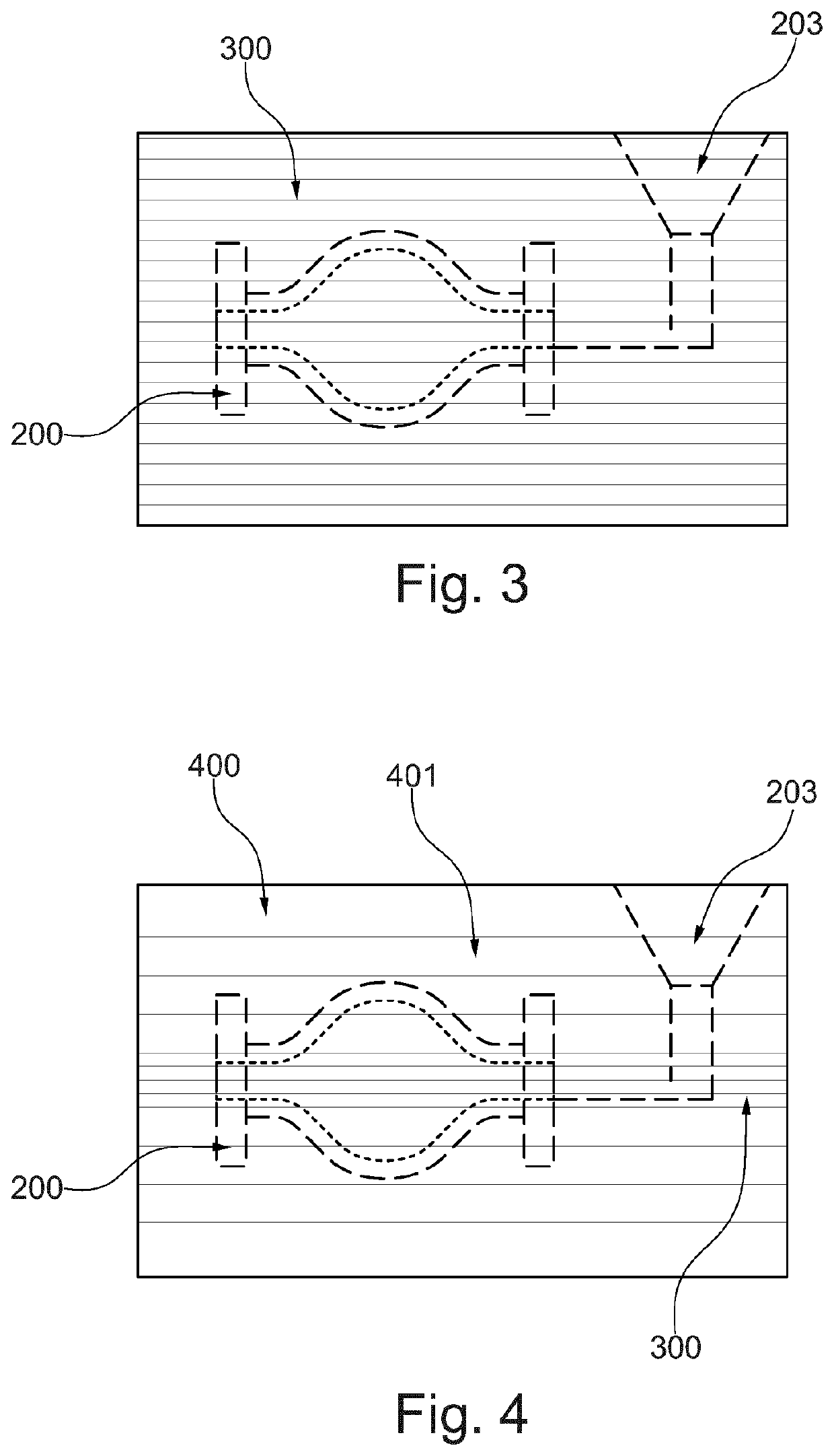
[0008]The above-mentioned method also allows the production of complex casting molds which can be composed of laminate bodies in layers, the individual laminate bodies being able to be produced in various processes with little effort.
[0022]For this purpose, it can be provided, for example, that recesses penetrating the laminate bodies are made in said laminate bodies by means of a subtractive, in particular a cutting process, by punching, laser cutting, water cutting or by a chemical process. In addition to sawing, milling, for example, is also conceivable as a machining method. Machining by drilling, grinding, planing, flame cutting, compressed air blasting, sandblasting or eroding is also possible. If the cohesion of particles of the laminate bodies is suitably adjusted, parts of the laminate bodies can also be removed by using negative pressure / suction. A targeted reversal of magnetization can at least facilitate the process of subtractive machining when using magnetic particles as the base material for the laminate bodies.
[0025]The maximum angle that two mutually opposite boundary surfaces of a laminate body form with one another should be limited and be less than 30 degrees, in particular less than 10 degrees, further in particular less than 1 degrees, so that the stacking direction or the alignment of the individual laminate bodies over the height of the stack does not vary too much and cohesion of the laminate body can be made possible in a simple manner. In some constellations, it can be advantageous to provide a number of wedge-shaped laminate bodies which follow one another in the stack in the opposite wedge direction or in an alternating wedge direction.
[0026]The method can also provide that each of the laminate bodies is free of undercuts in the stacking direction. The production of the individual laminate bodies is facilitated in this way, since, for example, machining can follow from one side of the laminate body in a simple manner. If undercuts are to be provided in the stacking direction in the cavity of the casting mold, then these undercuts can be implemented at least partially through the interfaces of the laminate bodies.
[0028]In addition to the method steps used directly to produce the laminate bodies and the casting mold, the method can also comprise a planning step, the planning being based on a model of the casting mold and said model being tentatively divided into one or more stacks of laminate bodies in a plurality of stacking directions. The selection of the stacking direction and optionally also the layer thickness of the laminate bodies can be made according to various optimization criteria. For example, the number of laminate bodies in the casting mold can be minimized, or the unevenness resulting from the interfaces between the laminate bodies in the casting mold can be minimized. The position of the undercuts in the casting mold can also be optimized in this way.

Problems solved by technology

Lost molds enable particularly complex cast products based on the decanting molding process, which is based on the destruction of the molds.
The disadvantage of such methods for producing casting molds is their high costs and long production times.

Method used


Image

  • Method for producing a casting mold and mold produced using the method
  • Method for producing a casting mold and mold produced using the method
  • Method for producing a casting mold and mold produced using the method

Examples


Embodiment Construction

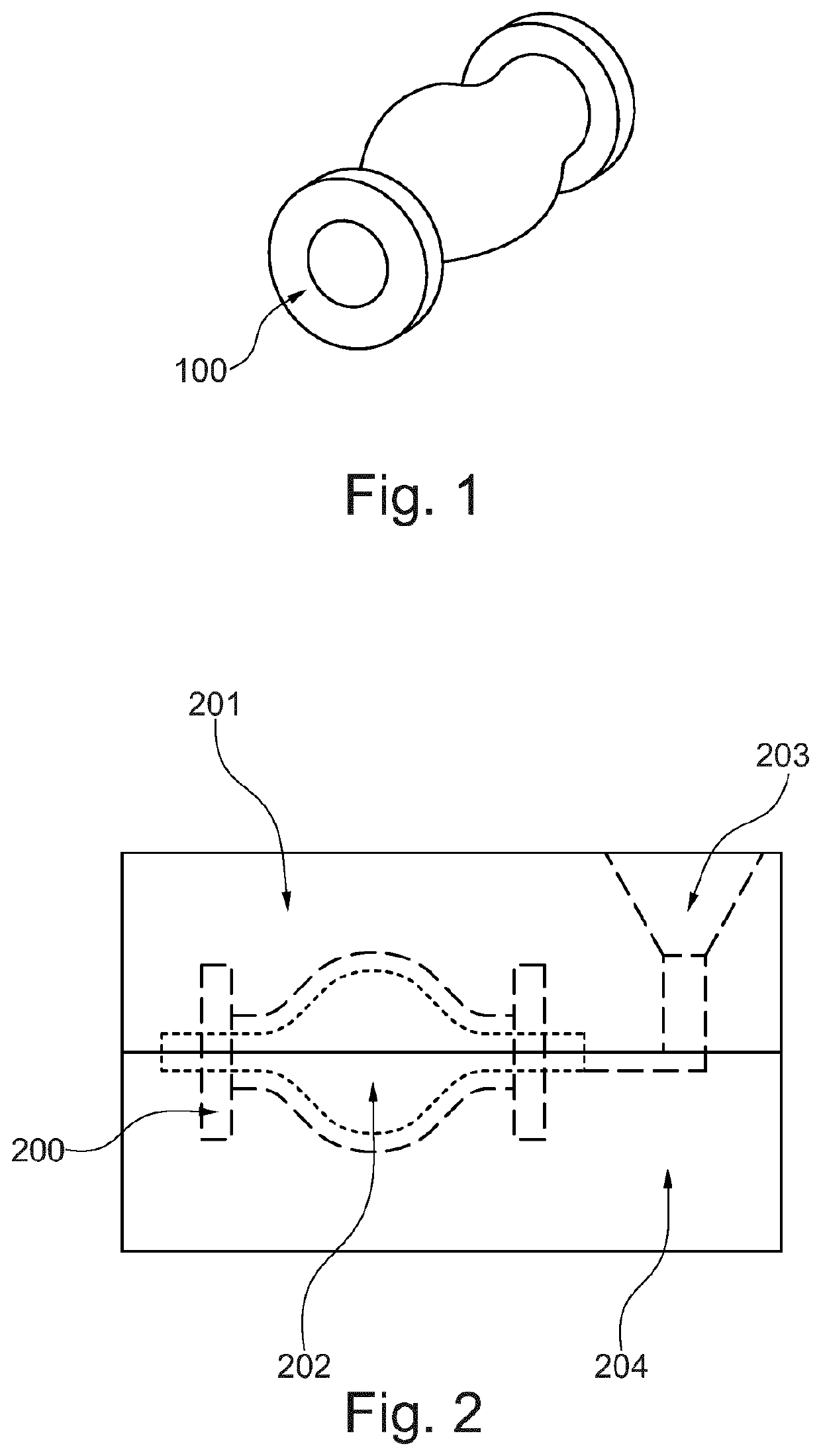
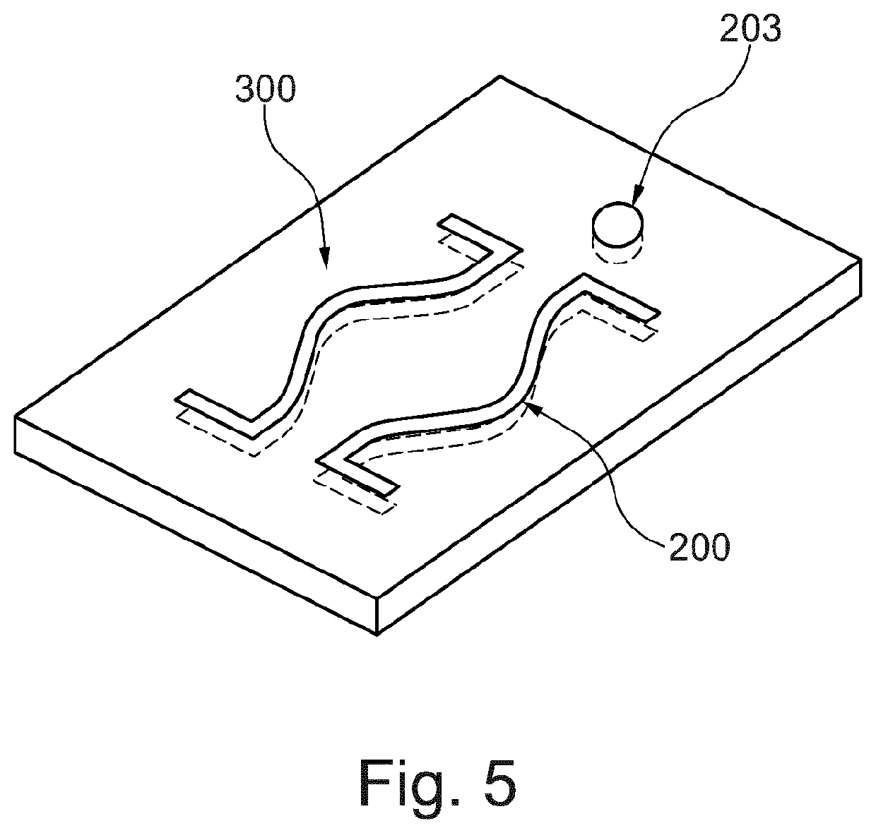
[0105]A bridge geometry over a pond is required for a horticultural project. The treads should be implemented with the aid of boards. The edges to the left and right of the steps are implemented by means of a topology-optimized lightweight structure, with different parts being connected to one another by individual support struts. The installation space of this structure is 900×600×600 mm3. The design of the bridge was calculated using mathematical optimization algorithms and does not exist in the form 201 of a physical model.

[0106]The bridge structure should be made of bronze for aesthetic reasons. A casting process is selected as the manufacturing process due to the very high complexity of the support structures. The foundry commissioned for this project sees the high level of complexity and opts for the method described above based on the favorable cost structure.

[0107]In preparation for the production of the mold, the bridge geometry is placed in a virtual installation space and...


PUM

PropertyMeasurementUnit
angleaaaaaaaaaa
angleaaaaaaaaaa
thickaaaaaaaaaa

Abstract

The invention relates to a method for producing a casting mold (201,204), according to which at least three, in particular at least four, five, more than five, or more than ten sandwich elements (300, 301, 302, 400, 401) of the casting mold are first produced separately from one another and are then combined into one or more stacks (1100) to form the casting mold.

Description

CROSS REFERENCE TO RELATED APPLICATIONS[0001]The present application is a national stage application of International Application No. PCT / EP2020 / 067242, filed Jun. 19, 2020, which claims priority to German Application No. 102019209047.8, filed Jun. 21, 2019, the disclosures of which are hereby incorporated by reference in their entireties.FIELD OF THE DISCLOSURE[0002]The invention is in the field of mechanics, mechanical engineering and foundry technology. Said invention can be used with particular advantage in the production of casting molds, its use in large casting molds, for example, in the construction of houses, parts of houses or other large components, being just as conceivable as in casting molds for small parts. In addition, the casting molds produced can be used for casting processes with many different casting materials.BACKGROUND OF THE DISCLOSURE[0003]Basically, so-called lost molds and permanent molds with and without cores are known as casting molds for the productio...

Claims


Application Information

Patent Timeline
Patent Type & Authority Applications(United States)
IPC IPC(8): B22C7/02
CPCB22C7/02B22C9/00
Inventor GÜNTHER, DANIELETTEMEYER, FLORIAN
Owner FRAUNHOFER GESELLSCHAFT ZUR FOERDERUNG DER ANGEWANDTEN FORSCHUNG EV
Why Eureka
Try Eureka