
Trailer Crank Extension Device for Automated Raising and Lowering of a Trailer

Pending Publication Date: 2022-11-10
MACDONALD ALBERT W
View PDF0 Cites 0 Cited by
  • Summary
  • Abstract
  • Description
  • Claims
  • Application Information

AI Technical Summary

Benefits of technology

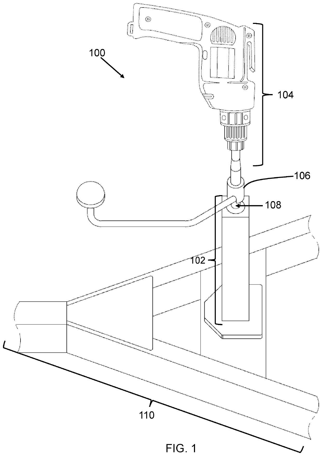
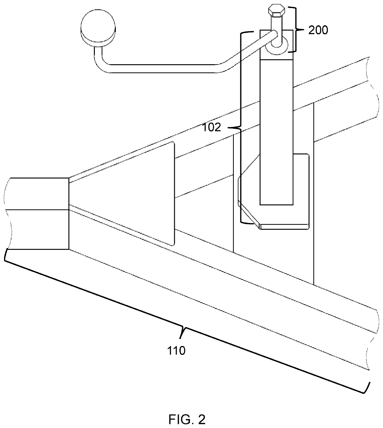
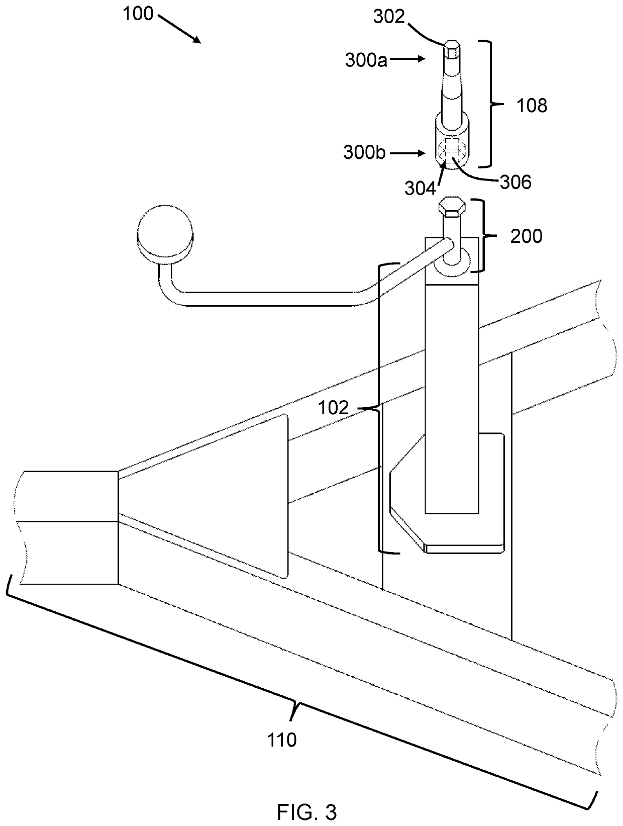
This patent is about a device that automates the raising and lowering of a trailer by attaching to a crank on the trailer and using a rotary tool. It is designed to save time and reduce strain on the user's body. The device can be attached to different types of cranks and is easy to manufacture. Additionally, it includes a strap to secure the device to the crank and a cross-shaped design to improve grip with the jaws of a chuck. The device also reduces bending over and torque on the back while lowering and raising a trailer. The goal is to provide an efficient and cost-effective solution for raising and lowering trailer jacks.

Problems solved by technology

However, this type of manually operated jack is often disfavored because of the amount of time and effort it takes to raise and lower the trailer.
However, often times this is problematic because of the substantial time it may take to lift and lower the trailer in such a manner.
However, there are problems with doing so.
For example, the time and expense of the install and rework necessary to install a hydraulic jack and the possibility of weakening the tongue or frame of the trailer as a result of the install are problematic.
Such a retrofit involves cutting into the trailer, damaging the powder coating, paint or other finish of the trailer.
Thus, this solution is particularly disfavored when the trailer is new or in good condition.
However, the hydraulic option has issues with leaking hydraulic fluid after a duration.
The problem with these trailer crank devices is that they do not magnify the force applied to the rotary crank, and they are not compactable for all types of trailers.
Also, the handle used to control the trailer crank device does not securely remain fixed to the trailer crank.

Method used


Image

  • Trailer Crank Extension Device for Automated Raising and Lowering of a Trailer
  • Trailer Crank Extension Device for Automated Raising and Lowering of a Trailer
  • Trailer Crank Extension Device for Automated Raising and Lowering of a Trailer

Examples


Embodiment Construction

[0045]The following detailed description is merely exemplary in nature and is not intended to limit the described embodiments or the application and uses of the described embodiments. As used herein, the word “exemplary” or “illustrative” means “serving as an example, instance, or illustration.” Any implementation described herein as “exemplary” or “illustrative” is not necessarily to be construed as preferred or advantageous over other implementations. All of the implementations described below are exemplary implementations provided to enable persons skilled in the art to make or use the embodiments of the disclosure and are not intended to limit the scope of the disclosure, which is defined by the claims. For purposes of description herein, the terms “upper,”“lower,”“left,”“rear,”“right,”“front,”“vertical,”“horizontal,” and derivatives thereof shall relate to the invention as oriented in FIG. 1. Furthermore, there is no intention to be bound by any expressed or implied theory pres...


PUM


Abstract

A trailer crank extension device for automated raising and lowering of a trailer automates the raising and lowering of a trailer by detachably mounting to a trailer crank, and coupling to a rotary tool that transfers torque, through the rod, to the rotatable drive shaft in the trailer crank. The device includes a rod having a male end and an opposing female end. The female end of the rod has a channel that receives and detachably fastens to a rotatable drive shaft of trailer crank. The male end comprises a geometric-shaped terminus, and projects out to engage and grip the chuck of a rotary tool. A cylindrical clamp removably encapsulates and fastens the female end of the rod with rotatable drive shaft of trailer crank. A rotary tool couples to the male end of rod to rotate, and thereby transfer torque, to the rotatable drive shaft, through the rod.

Description

FIELD OF THE INVENTION[0001]The present invention relates generally to a trailer crank extension device for automated raising and lowering of a trailer. More so, the present invention relates to a trailer crank accessory that automates raising and lowering of a trailer by detachably coupling to the rotatable drive shaft of a trailer crank, and receiving a rotary tool that transfers torque, through the extension device, to the rotatable drive shaft in the crank of the trailer for raising and lowering the trailer.BACKGROUND OF THE INVENTION[0002]The following background information may present examples of specific aspects of the prior art (e.g., without limitation, approaches, facts, or common wisdom) that, while expected to be helpful to further educate the reader as to additional aspects of the prior art, is not to be construed as limiting the present invention, or any embodiments thereof, to anything stated or implied therein or inferred thereupon.[0003]Typically, a trailer include...

Claims


Application Information

Patent Timeline
IPC IPC(8): B60S9/08
CPCB60S9/08B25B13/5091
Inventor MACDONALD, ALBERT W.
Owner MACDONALD ALBERT W
Learn More