A Layered Protective Structure For Protective Garments And Equipment And An Elastic Layer

a protective structure and elastic layer technology, applied in the direction of protective garments, garments, sport apparatus, etc., can solve the problems of inability of the piece to effectively distribute shock over a wider area, discomfort and fatigue, and the inability so as to reduce the probability of injuries, and improve the effect of impact spreading

Pending Publication Date: 2022-11-17
IBP TECH OY
View PDF0 Cites 1 Cited by
  • Summary
  • Abstract
  • Description
  • Claims
  • Application Information

AI Technical Summary

Benefits of technology

[0033]It is an advantage of the invention that it provides a layered protective structure that is light and has efficient air circulation. The invention also allows the use of heavy elastic materials which usually cannot be used or have only limited use due their weight.
[0034]Using the layered protective structure significantly improves impact-spreading and thus diminishes the probability of injuries. It also makes for a product that has no complex parts, so that it is easier to manufacture and maintain than devices according to known techniques.
[0035]One advantage of the invention is that it is quite durable and retains its form but is still elastic. The layered protective structure can also be easily and quickly integrated in different kinds of garments and equipment. It also allows an embodiment where the second layer is elastic when subjected to light impacts and the second layer stiffens when subjected to a sufficiently forceful impact. This makes it possible to construct protective structures that can withstand and protect the user from more powerful impacts than known techniques. This feature guides air circulation and improves the impact durability of the layered protective structure. It also prevents the first layer from breaking or shattering.
[0036]It is a further advantage of the invention that additional devices, such as sensors, can be easily integrated in the layered protective structure. Also, the invention makes it possible, due its lightness and efficient air circulation, to use the layered protective structure in, for example, safety garments for elderly people.

Problems solved by technology

A protective structure made of a sheet-like material by die-cutting inevitably becomes fairly heavy.
The thickness of the material is the same throughout the whole piece and the ability of the piece to distribute shocks effectively over a wider area remains rather limited.
The described protective structure also traps heat and prevents air from circulating under the protective structure, causing discomfort and fatigue.
Further, this kind of construct may increase the weight of the protective structure and prevent air circulation.
Also, there is a possibility of the protective structure of some parts of it breaking or shattering of the when the protective structure is subjected to a sufficiently forceful impact.

Method used


Image

  • A Layered Protective Structure For Protective Garments And Equipment And An Elastic Layer
  • A Layered Protective Structure For Protective Garments And Equipment And An Elastic Layer
  • A Layered Protective Structure For Protective Garments And Equipment And An Elastic Layer

Examples


second embodiment

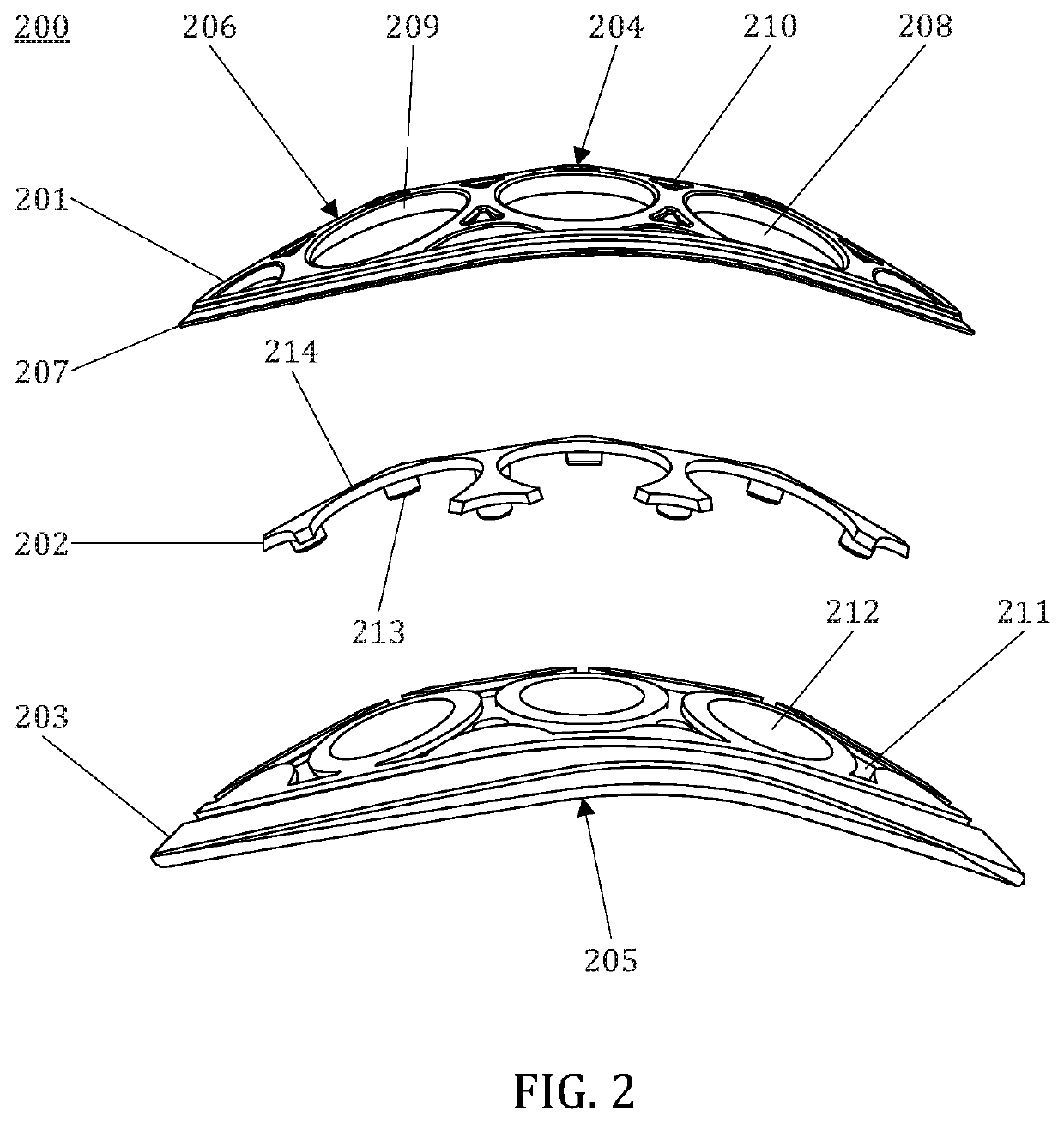
[0068]FIG. 2 shows a protective structure 200 as seen from side. The layers are separated from each other for the sake of clarity. The protective structure has a first surface 204 and a second surface 205 and comprises at least three layers: a first layer 201, a second layer 202 and a third layer 203.

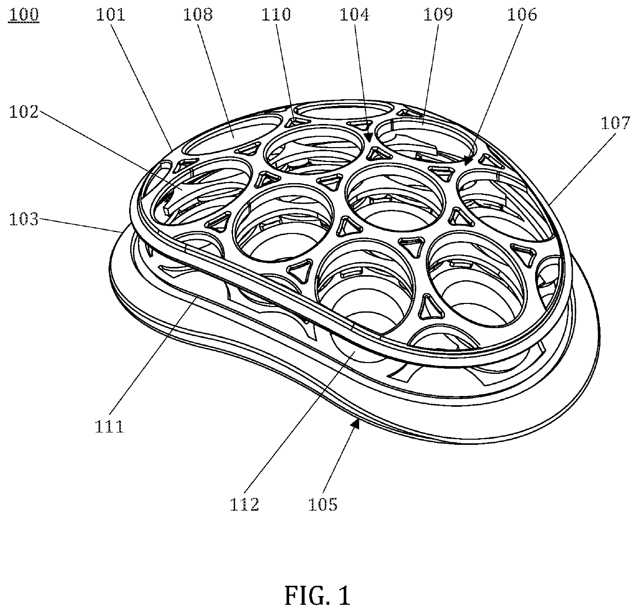
[0069]The first layer comprises a mesh structure 206 and a border frame 207. The mesh structure has a multitude of first layer holes 208 extending through the first layer. Between the holes are rib structures that form the frame of the mesh structure, and one surface of the rib structures forms the outer surface of the protective structure 200, i.e., the first surface 204. The first layer is slightly curved. The middle point, i.e., the top point of the mesh structure is located higher than the border frame (i.e., the top point is vertically farthest from the border frame plane). Even the slightly outward (i.e., the direction away from the user of the protective structure when the protec...

third embodiment

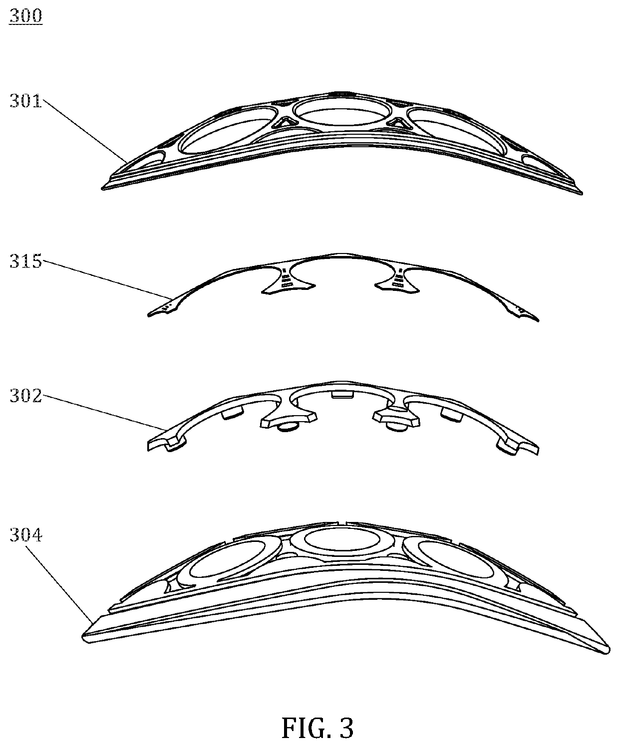
[0072]The third layer 203 comprises third layer holes 212 and third layer grooves 211 to receive both parts of the first layer 201 and the second layer 202. In some embodiments the first layer and the third layer are fixed to each other. The fixing can be done by, for example, knitting, stapling, gluing or a similar means, the border frame 207 to the third layer material. FIG. 3 shows a protective structure 300 as seen from side. The layers are separated from each other for the sake of clarity. The protective structure comprises at least three layers: a first layer 301, a second layer 302 and a third layer 303. Between the first layer and the second layer is placed a sensor arrangement 315. The sensor arrangement includes sensors, for example acceleration sensors, and connectors to external devices. In this example the sensor arrangement is a thin flexible printed circuit board. Naturally, the sensor arrangement can be placed and implemented differently.

fourth embodiment

[0073]FIG. 4 shows a protective structure 400 as seen from the side. The layers are separated from each other for the sake of clarity. The protective structure comprises at least three layers: a first layer 401, a second layer and a third layer 403. In this embodiment the second layer has two parts: a first second layer part 402a and a second second layer part 402b. The second layer parts are fixed to each other when the protective structure is manufactured. If the second layer is molded, having a two-part second layer makes it possible to implement hollow second layer bugles. In some embodiments the hollow second layer bugles share the elastic properties of the second layer. Also, it makes the second layer lighter. The protective structure further comprises a sensor arrangement 415. The sensor arrangement can be placed between the second layer parts when fixing the second layer parts together. In that way the sensor arrangement is quite well protected because the second layer stret...


PUM


Abstract

A layered protective structure for protective garments and equipment is disclosed. The layered protective structure comprises three layers. The first layer is the outermost layer, and it is the most rigid of the layers and has first layer holes that have at their edges rim structures extending inward into the protective structure. The second layer is an elastic net-like structure that is configured to fit at least partly between the rim structures. The first layer and the second layer are on top of the third layer, which is the innermost of the layers (i.e., towards the user when the protective structure is in use). The third layer is made of a softer and more flexible material than the first layer. The second layer spreads the impact forces and conveys at least part of them to the third layer.

Description

CROSS REFERENCE TO RELATED APPLICATIONS[0001]This application is a national phase application of international application PCT / FI2020 / 000012, filed Jun. 26, 2020 and further claims priority to Finnish patent application FI20197098, filed 28 Jun. 2019, the content of both of which is herein incorporated by reference.BACKGROUND OF THE INVENTION[0002]The invention relates to a layered protective structure for protective garments and equipment, comprising three layers: a first layer, a second layer and a third layer, and the protective structure is configured to be positioned in a garment or equipment in such a way that the third layer is the nearest layer to the user of the garment or equipment and the first layer is the farthest layer from the user, and the first layer comprises a first surface, a second surface and a mesh structure having a multitude of first layer holes extending from the first surface to the second surface. The invention relates also to an elastic layer for a layer...

Claims


Application Information

Patent Timeline
Patent Type & Authority Applications(United States)
IPC IPC(8): A41D31/28A41D13/015A41D13/05A41D31/18
CPCA41D31/285A41D13/0158A41D13/05A41D31/185A41D13/0156A63B71/08A63B71/12B32B3/30B32B3/266
Inventor NYLUND, MAURI
Owner IBP TECH OY
Why Eureka
Try Eureka