Fuel pump with inlet valve assembly

Pending Publication Date: 2022-11-17
DELPHI TECH IP LTD
View PDF3 Cites 0 Cited by
  • Summary
  • Abstract
  • Description
  • Claims
  • Application Information

AI Technical Summary

Benefits of technology

The patent describes a fuel pump with an inlet valve assembly that can selectively control fluid communication between the pump and the chamber. The invention includes a sealing ring made of elastomer material that is compressed against the fuel pump and the outer housing, which minimizes the likelihood of liquids from the exterior environment from reaching the inlet valve assembly and causing undesired operation. The technical effect of this invention is to improve the reliability and efficiency of the fuel pump by preventing liquids from entering its inlet valve assembly.

Problems solved by technology

During operation, the internal combustion engine is subject to varying demands for output torque.
However, portions of the inlet valve assembly which extend outside of the fuel pump housing may be exposed to environmental conditions which may cause liquids, such as rainwater or saltwater from deiced roadways, from being deposited on the outlet control valve.
These liquids may seep into interfaces of components that form the inlet control valve or solenoid and over time may compromise one or more of the components of the inlet control valve or solenoid which may lead to undesired operation of the inlet control valve.

Method used


Image

  • Fuel pump with inlet valve assembly
  • Fuel pump with inlet valve assembly
  • Fuel pump with inlet valve assembly

Examples


Embodiment Construction

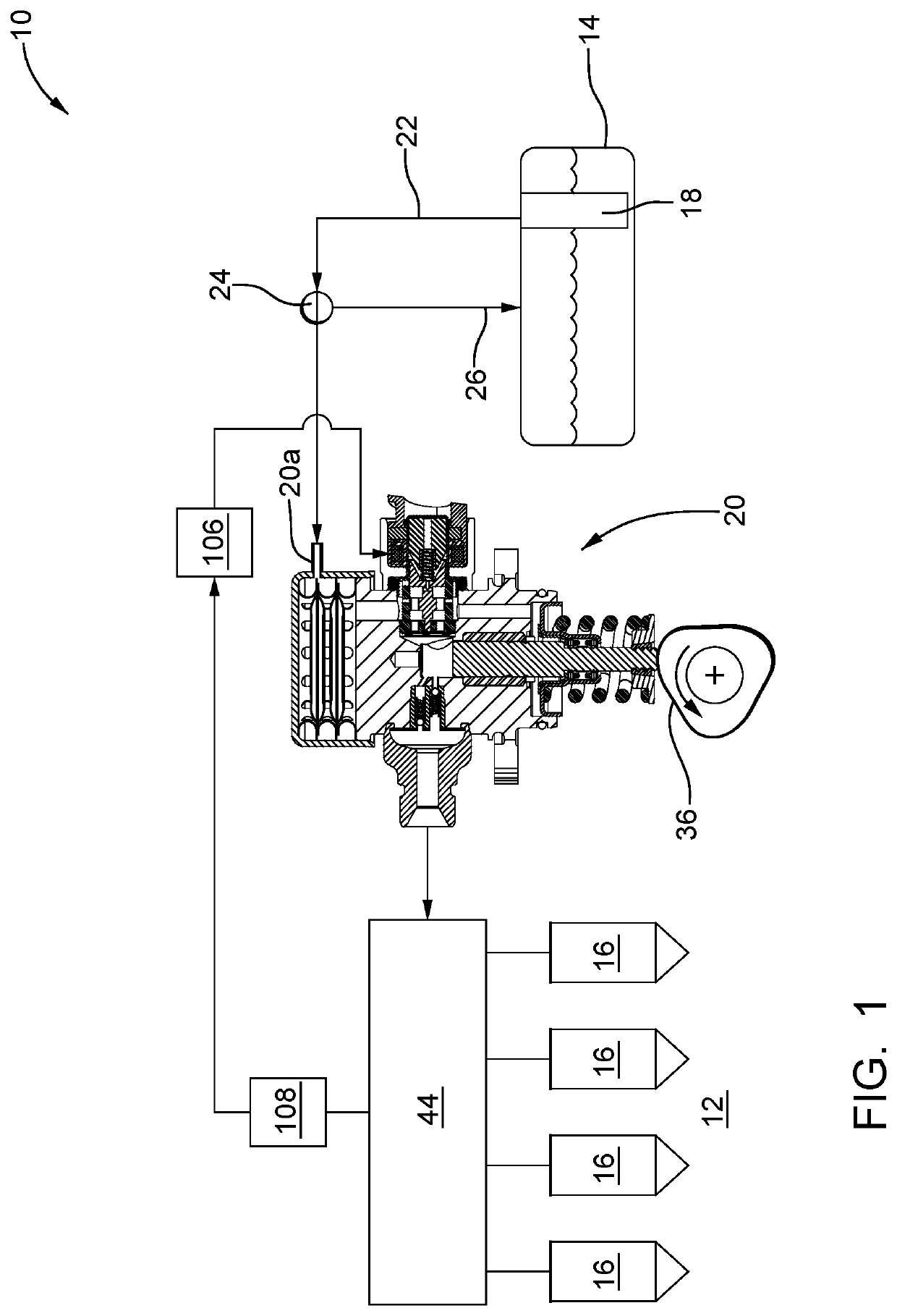
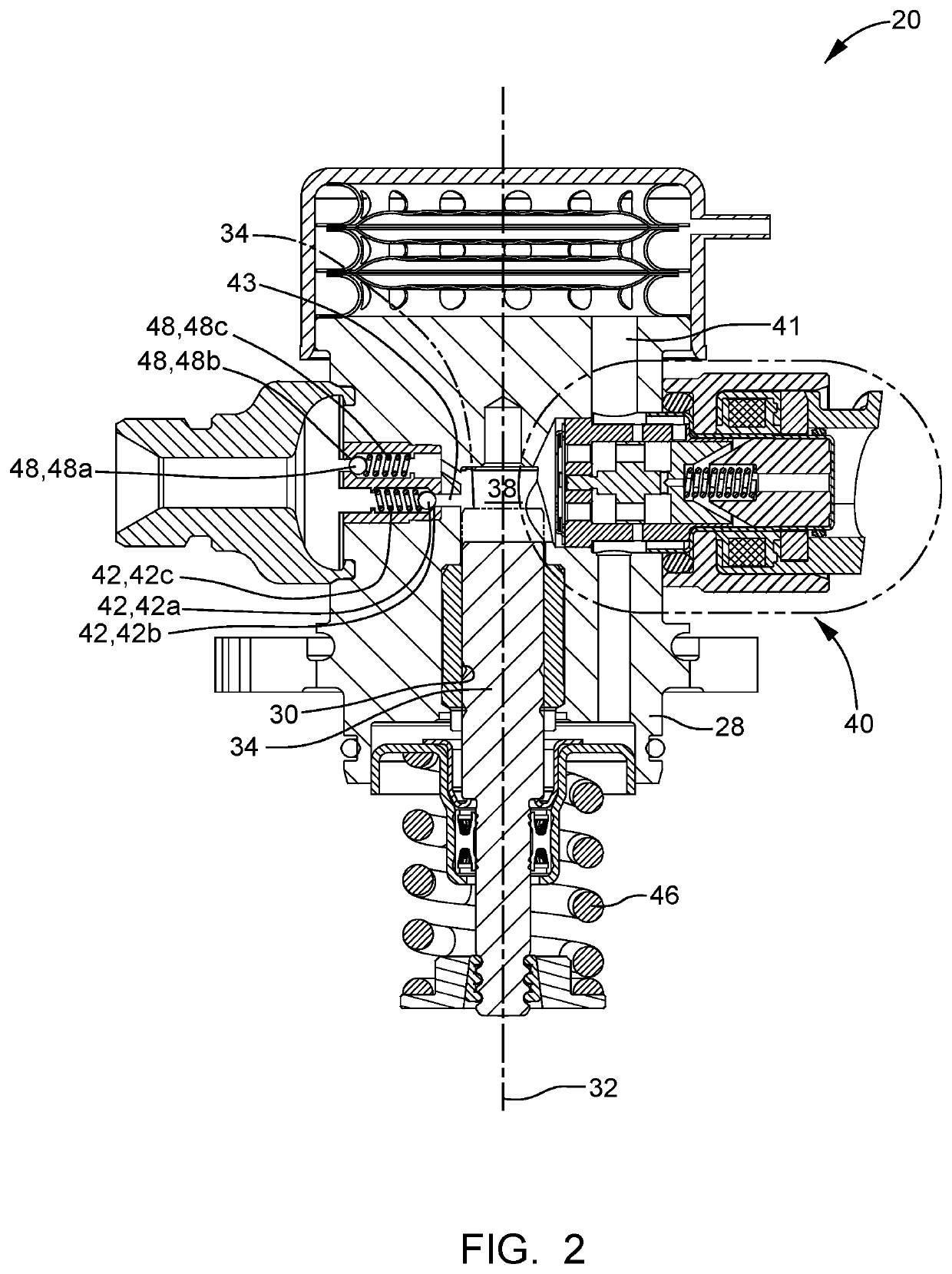
[0015]In accordance with a preferred embodiment of this invention and referring initially to FIG. 1, a fuel system 10 for an internal combustion engine 12 is shown is schematic form. Fuel system 10 generally includes a fuel tank 14 which holds a volume of fuel to be supplied to internal combustion engine 12 for operation thereof; a plurality of fuel injectors 16 which inject fuel directly into respective combustion chambers (not shown) of internal combustion engine 12; a low-pressure fuel pump 18; and a high-pressure fuel pump 20 where the low-pressure fuel pump 18 draws fuel from fuel tank 14 and elevates the pressure of the fuel for delivery to high-pressure fuel pump 20 where the high-pressure fuel pump 20 further elevates the pressure of the fuel for delivery to fuel injectors 16. By way of non-limiting example only, low-pressure fuel pump 18 may elevate the pressure of the fuel to about 500 kPa or less and high-pressure fuel pump 20 may elevate the pressure of the fuel to above...


PUM


Abstract

A fuel pump includes a pump housing with a pumping chamber an inlet valve bore. An inlet valve selectively provides and prevents fluid communication between an inlet of the fuel pump and the pumping chamber. The inlet valve includes an inner housing received within the inlet valve bore such that an outer periphery of the inner housing is sealed to an inner periphery of the inlet valve bore. An outer housing circumferentially surrounds the inner housing. An annular chamber is defined radially between the inner housing and the outer housing and axially between the outer housing and the pump housing. A sealing ring is located within the annular chamber such that the sealing ring is compressed axially against the pump housing and the outer housing.

Description

TECHNICAL FIELD OF INVENTION[0001]The present invention relates to a fuel pump which supplies fuel to an internal combustion engine, more particularly to such a fuel pump which includes an inlet valve assembly, and even more particularly to such a fuel pump with an inlet valve assembly which is robust to exterior environmental fluid exposure.BACKGROUND OF INVENTION[0002]Fuel systems in modern internal combustion engines fueled by gasoline, particularly for use in the automotive market, employ gasoline direct injection (GDi) where fuel injectors are provided which inject fuel directly into combustion chambers of the internal combustion engine. In such systems employing GDi, fuel from a fuel tank is supplied under relatively low pressure by a low-pressure fuel pump which is typically an electric fuel pump located within the fuel tank. The low-pressure fuel pump supplies the fuel to a high-pressure fuel pump which typically includes a fuel pump housing and a pumping plunger which is re...

Claims


Application Information

Patent Timeline
IPC IPC(8): F02M59/46F02M59/02F02M59/36
CPCF02M59/466F02M59/027F02M59/464F02M59/367F02M55/004F02M59/366F02M2200/16F02M59/445F04B49/243
Inventor KASWER, BRANDONSPAKOWSKI, JOSEPH G.
Owner DELPHI TECH IP LTD
Why Eureka
Try Eureka