Wireless emergency safety light with sensing means for conventional light switch or plug receptacle

a technology of emergency safety light and conventional light switch, which is applied in the direction of emergency power supply arrangement, power supply with built-in power, lighting and heating apparatus, etc., can solve the problems of easy installation and device housing disclosur

Inactive Publication Date: 2000-01-04
BLACKMAN STEPHEN E
View PDF7 Cites 343 Cited by
  • Summary
  • Abstract
  • Description
  • Claims
  • Application Information

AI Technical Summary

Benefits of technology

Accordingly, a primary advantage of the present invention is that it provides a simple and easily installable wireless emergency safety light which includes a fixedly-attached housing for the replacement of a standard switch plate or standard receptacle plate and which activates itself in response to a power failure of any kind.Another advantage of the present invention is that it provides a housing for a wireless emergency safety light which is mechanically connectable to a conventional light switch.Another advantage of the present invention is that it provides a wireless emergency safety light which is battery operated and can operate with different types of light sources, such as LED lamps, a fluorescent lamp, an incandescent lamp, or an electroluminescent film.Another advantage of the present invention is that it provides a wireless emergency safety light which has an antenna sensing device for sensing a power failure and for automatically actuating the emergency light source.Another advantage of the present invention is that it provides for a wireless emergency safety light in which an antenna sensing device is capable of receiving a radio frequency signal that is emitted from all electrical wiring when electrical current is present, such that the antenna sensing device detects the presence and / or loss of electrical power and activates the wireless emergency safety light.A further advantage of the present invention is that it provides a multi-position switch for selecting a motion sensor, a timer, a night light, or a photocell.A still further advantage of the present invention is that it provides a housing for a wireless emergency safety light which can be mass produced in an automated and economical manner and is relatively inexpensive.A latitude of modification, change, and substitution is intended in the foregoing disclosure, and in some instances, some features of the invention will be employed without a corresponding use of other features. Accordingly, it is appropriate that the appended claims be construed broadly and in a manner consistent with the spirit and scope of the invention herein.

Problems solved by technology

The prior art devices do not disclose a housing which is easily installable and mechanically connectable to a conventional light switch to provide automatic illumination to an area when a power failure occurs.

Method used


Image

  • Wireless emergency safety light with sensing means for conventional light switch or plug receptacle
  • Wireless emergency safety light with sensing means for conventional light switch or plug receptacle
  • Wireless emergency safety light with sensing means for conventional light switch or plug receptacle

Examples


first embodiment

DETAILED DESCRIPTION OF THE FIRST EMBODIMENT

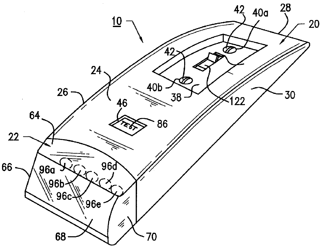
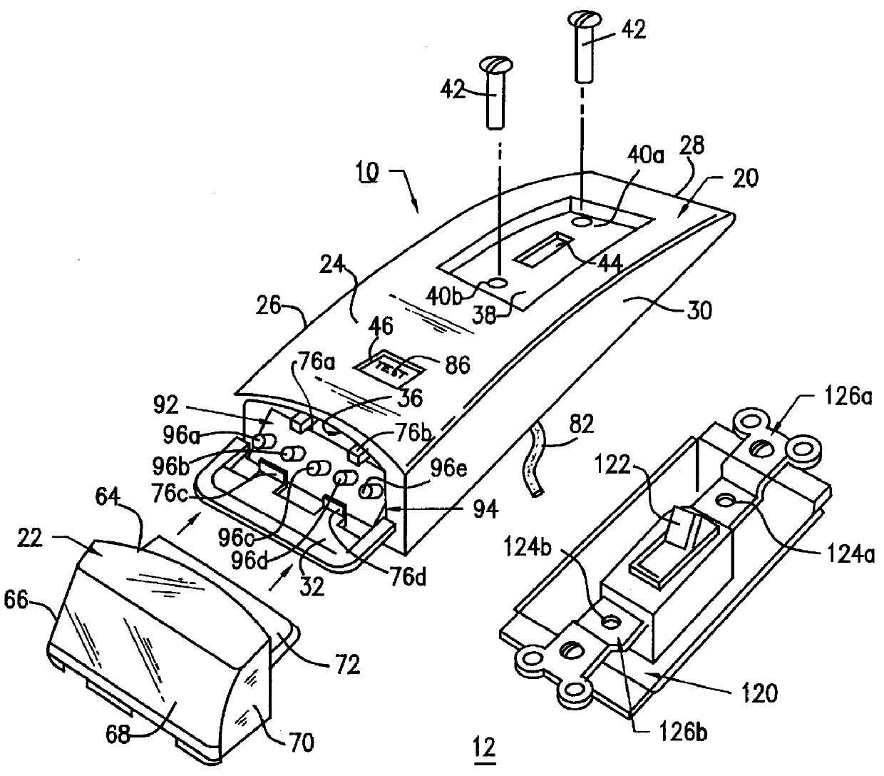
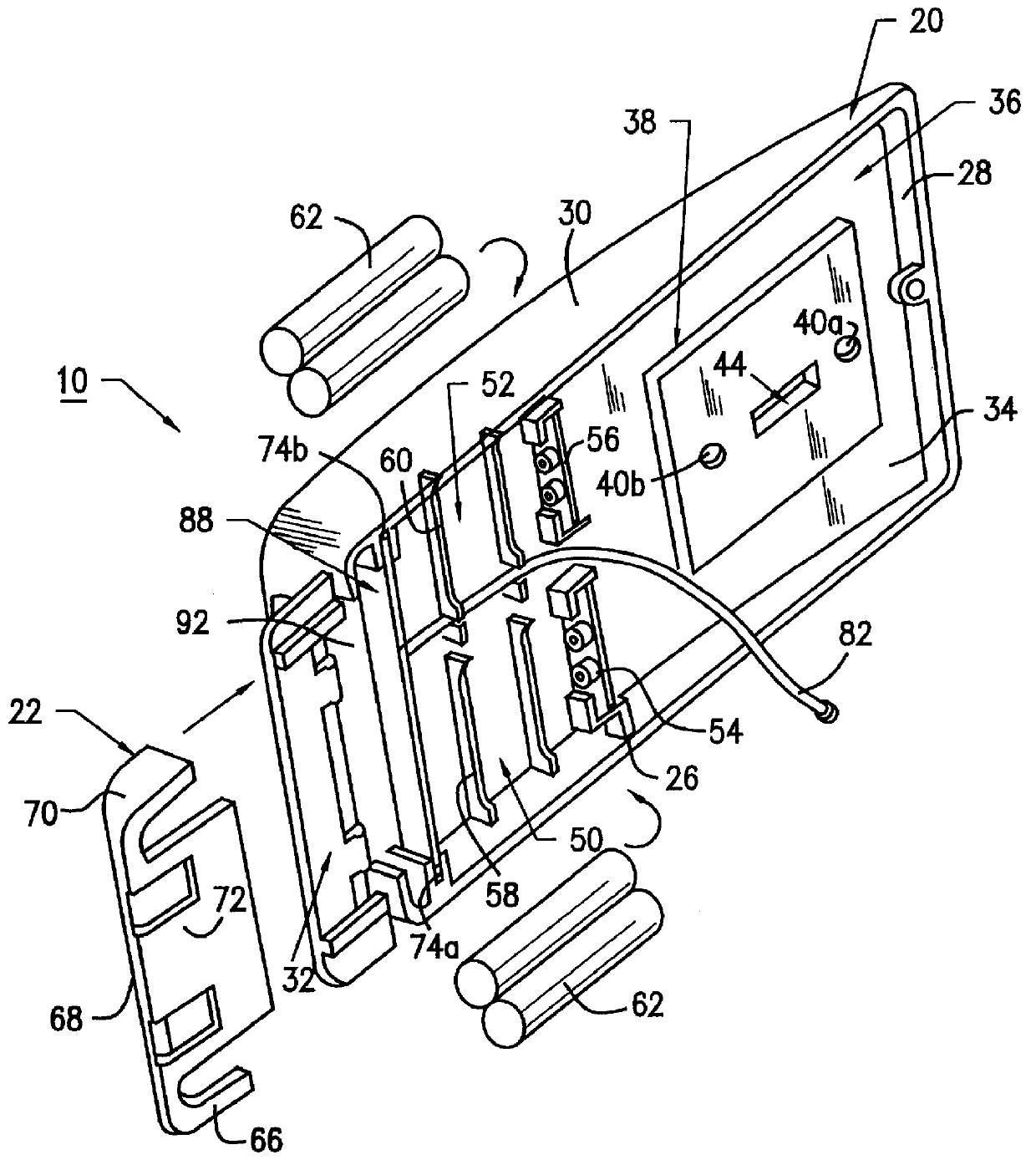
The first embodiment of the present invention provides for a wireless emergency safety light 10, as represented in detail by FIGS. 1 through 5 of the drawings. The wireless emergency safety light 10 includes a housing 20 having a lower lens cover section 22. The housing 20 includes a front wall 24, side walls 26, 28 and 30, a bottom wall 32 for receiving the lens cover section 22, a rear wall 34, and an interior cavity 36 for holding in place an electrical assembly 80 therein. Front wall 24 includes an upper cavity section 38 having a pair of mounting hole openings 40a and 40b for receiving mounting screws 42 for mounting housing 20 to the wall junction box assembly 120; and a rectangular shaped switch opening 44 for receiving wall switch 122 of the wall junction box assembly 120. In addition, front wall 24 also includes a test switch opening 46 for receiving a test switch actuator 86 attached to electrical assembly 80. Mounting screws 42 ...

second embodiment 200

The wireless emergency safety light of the second embodiment 200 of the present invention is depicted in detail by FIG. 6 of the drawings. All aspects of the wireless emergency safety light 200 of the second embodiment are the same as the wireless emergency safety light 10 of the first embodiment, except for the design and configuration of the front wall 224 having an upper cavity section 238 of housing 220. Safety light 200 includes a housing 220 having a front wall 224 with an upper cavity section 238. Upper cavity section 238 includes a plurality of mounting hole openings 240a, 240b, 240c, and 240d for receiving mounting screws 42 for mounting housing 220 to the wall junction box assembly 210; and a pair of rectangular-shaped switch openings 244a and 244b for receiving wall switches 212a and 212b of the wall junction box assembly 210. In all other respects, the wireless emergency safety light 200 of the second embodiment functions and operates in use in the same manner as the wir...

third embodiment 300

The wireless emergency safety light of the third embodiment 300 of the present invention is depicted in detail by FIG. 7 of the drawings. All aspects of the wireless emergency safety light 300 of the third embodiment are the same as the wireless emergency safety light 10 of the first embodiment, except for the design and configuration of the front wall 324 having an upper cavity section 338 of housing 320. Safety light 300 includes a housing 320 having a front wall 324 with an upper cavity section 338. Front wall 324 includes a pair of mounting hole openings 340a and 340b for receiving mounting screws 42 for mounting housing 320 to the wall junction box assembly 310. Upper cavity section 338 includes a rectangular-shaped switch opening 344 for receiving one or more enlarged rocker switches 312 of the wall junction box assembly 310. In other respects, the wireless emergency safety light 300 of the third embodiment functions and operates in use in the same manner as the wireless emerg...


PUM


Abstract

A housing for a wireless emergency safety light which is mechanically connectable to a conventional light switch for a light fixture or a plug receptacle for providing power to a load. The housing replaces a conventional switch plate having at least one opening for receiving the switch actuator of the light switch or for receiving the electrical plug receptacle. The emergency safety light includes at least one compartment in the housing for receiving batteries; a second compartment in the housing for receiving an emergency light source adapted to be connected to the batteries; and an antenna for sensing the loss of electrical power to the light switch and, in response thereto, for actuating the emergency light source.

Description

The invention relates to a housing for a wireless emergency light source and, more particularly, a wireless emergency light source for automatically illuminating an area in response to a power failure.This invention is a further improvement of the inventions set forth in U.S. Pat. No. 5,473,517 and U.S. application Ser. No. 08 / 566,677 and relates to a unit that replaces a conventional switch or plug receptacle for controlling any electrical load, such as a light fixture or appliance, in response to a power failure.Frequently, homes, offices, and industrial plant facilities experience many types of emergency situations involving power failures where an interior or exterior area has no light. The power failures may be caused by electrical short circuits, brownouts, fire, accidents, natural disasters (i.e., floods, hurricanes, tornadoes, etc.), or a planned shutoff of electricity to a facility or dwelling. As a result of these emergencies, most facilities, and especially residential ho...

Claims


Application Information

Patent Timeline
Patent Type & Authority Patents(United States)
IPC IPC(8): F21V23/04F21S9/02F21S9/00H02J9/02H02J9/00
CPCF21S9/022F21V23/0442H02J9/02F21Y2101/02Y10S362/802F21Y2115/10
Inventor BLACKMAN, STEPHEN E.WOLFGANG, THOMAS
Owner BLACKMAN STEPHEN E
Why Eureka
Try Eureka