System and method to display raster images with negligible delay time and reduced memory requirements

a raster image and delay time technology, applied in the field of raster imagebased display technology, can solve the problems of insufficient raster image viewing applications available today, most applications are too slow to meet display requirements, and are too cumbersome to us

Inactive Publication Date: 2000-01-04
UNISYS CORP
View PDF13 Cites 31 Cited by
  • Summary
  • Abstract
  • Description
  • Claims
  • Application Information

AI Technical Summary

Problems solved by technology

There are no adequate raster image viewing applications available today to provide, in a single complete package, the necessary capabilities to filly implement an image-based document viewing system.
Most applications are too slow to meet display requirements (independent of the hardware platform) and are too cumbersome to use.
Additionally, most applications do not support the various raster image formats required, especially CCITT-4 format and numerous and varying strains of TIFF format.
Raster devices fail

Method used


Image

  • System and method to display raster images with negligible delay time and reduced memory requirements
  • System and method to display raster images with negligible delay time and reduced memory requirements
  • System and method to display raster images with negligible delay time and reduced memory requirements

Examples


Embodiment Construction

The image display process will now be described. FIG. 9 is a flow chart illustrating a raster image display process 900 according to a preferred embodiment of the present invention. Process 900 includes operational steps 902-922. Steps 902-908 represent initialization of an image data structure 502, shown in FIG. 5, and allocation of any resources to be employed by process 900. Steps 910-918 represent a main loop of process 900 in which original image 102 is decoded and transformed into display image 104 on a display strip by display strip basis. Steps 920-922 represents deallocation of resources employed by process 900. Steps 902-922 will now be described in more detail.

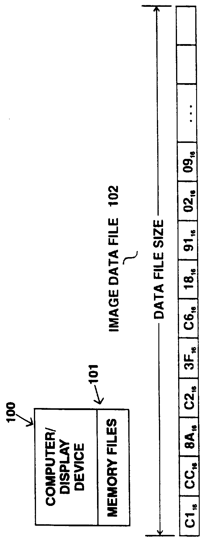
Referring to FIGS. 1, 5, and 9, process 900 beings in step 902 by determining the image, display, process flow, and optional input parameters. The image file name 511 is used to access the image data file 102 resident on a computer system and open it for reading.

Once opened, selected portions of image data file 102 ...


PUM


Abstract

The present invention is directed to a general purpose raster image system. The present invention performs transformations on an original raster image, and optimizes the raster image decoding and display techniques, to dramatically increase the display performance capabilities by a factor of up to fifteen times the performance provided by previous raster devices. The present invention employs two primary enhanced display features to produce fast raster image decode and display results: (1) data reduction and transformations and (2) optimized algorithmic implementations. Data reduction and transformations operate as follows: a raster image is divided into strips, which are processed individually. A feature of the optimized algorithmic implementation is to increase processing thruput of the display process by optimizing the use of available resources required to decode and display the raster images. In one embodiment, scaling operations are converted from calculation based algorithms, to data lookup tables indexed by the position of the raster image data in the original scan line. Raster image decoding algorithms are changed from iterative conditional loops to redundant code segments individually tailored for specific occurrences of raster image data. Additionally implementation of assembly language in time critical sections of display procedures allocates CPU register resources more efficiently and significantly increases performance.

Description

1. Field of the InventionThe present invention relates generally to raster image-based display technology. More specifically, the present invention relates to a system and method that enhances display rates of raster devices and reduces the quantity of memory needed to display a raster image.2. Related ArtThere are no adequate raster image viewing applications available today to provide, in a single complete package, the necessary capabilities to filly implement an image-based document viewing system. Most applications are too slow to meet display requirements (independent of the hardware platform) and are too cumbersome to use. Additionally, most applications do not support the various raster image formats required, especially CCITT-4 format and numerous and varying strains of TIFF format.Raster devices failing to meet the display time requirements exhibit three main problems: (1) they require large amounts of RAM to display large raster images; (2) several seconds elapse from the ...

Claims


Application Information

Patent Timeline
IPC IPC(8): G06T1/60
CPCG06T1/60
Inventor SALAMON, TED R.
Owner UNISYS CORP
Why Eureka
Try Eureka