Flood control system

a control system and flood control technology, applied in the direction of rigid containers, pliable tubular containers, transportation and packaging, etc., can solve the problems of insufficient quantity of sand for filling, the amount of human labor required for the installation of sand bags, and the difficulty of ensuring the safety of the sandbag

Inactive Publication Date: 2000-01-11
TOBOR & GOLDSTEIN
View PDF22 Cites 69 Cited by
  • Summary
  • Abstract
  • Description
  • Claims
  • Application Information

AI Technical Summary

Benefits of technology

In a more specific aspect, the flood control method includes the steps of: (a) locating a flood zone prior to flooding, the flood zone being proximate a body of water having a top surface, the body of water being susceptible to flooding whereby the top surface of the body of water rises and the water flows into, and onto, the flood zone; (b) locating a barrier zone proximate the flood zone; (c) providing a substantially level support surface within the barrier zone; (d) providing a plurality of substantially rigid containers, some of the substantially rigid containers having upper and lower portions, with substantially rigid sidewalls operably connecting the upper and lower portions; (e) providi...

Problems solved by technology

Sandbags, however, have a number of problems.
One of the problems with sandbags lies in the amount of human labor required for their installation.
Another problem is the need for sufficient quantities of sand for filling purposes.
When that is not the case, the necessary quantities of sand must be transported, which is expensive and time-consuming.
Yet another problem is the logistics of coordinating the human effort of transporting the sand, filling the bags and placing the bags at the right location within the appropriate time frame.
The sheer number of sandbags often makes this a Herculean task, which is exacerbated by the fact that it is often done in pouring rain.
Still another problem is that after flooding, once the waters have subsided, the sa...

Method used


Image

  • Flood control system
  • Flood control system
  • Flood control system

Examples


Embodiment Construction

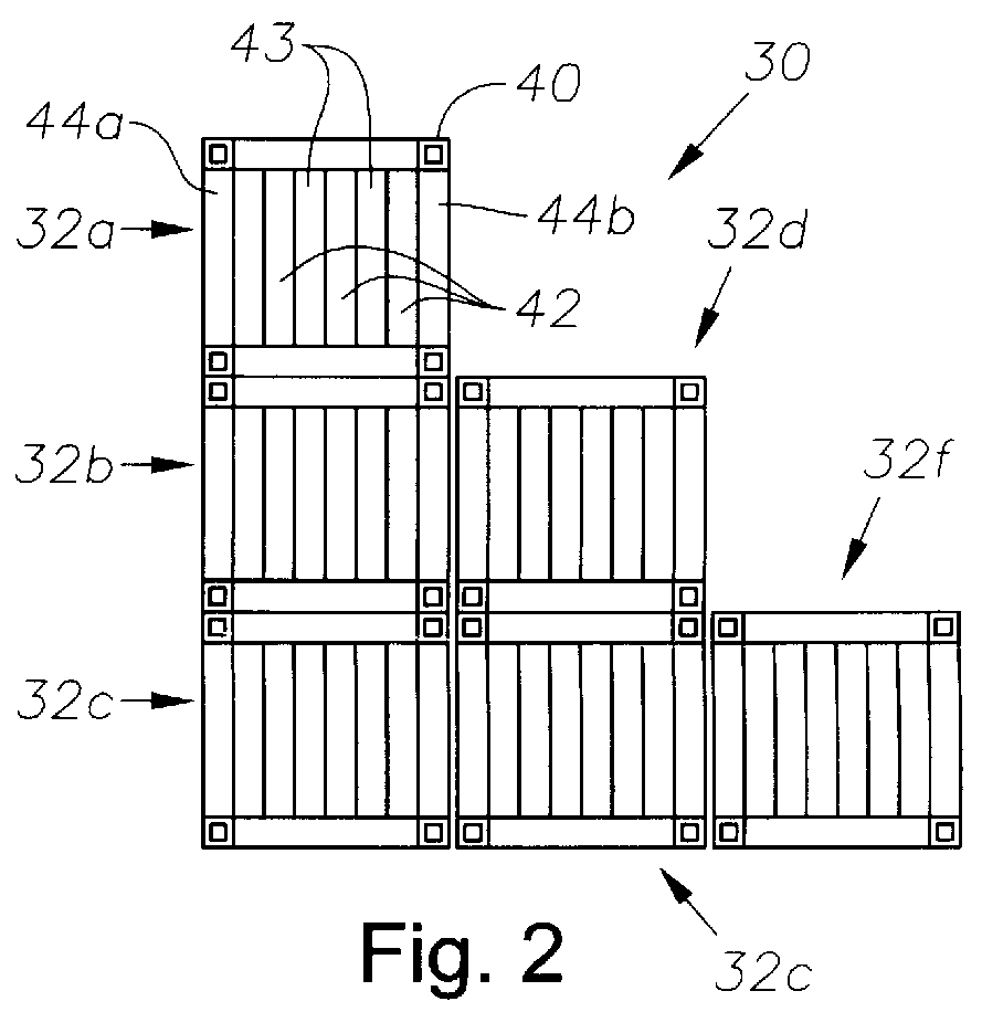
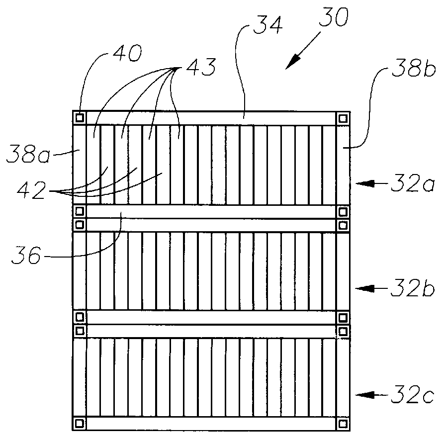
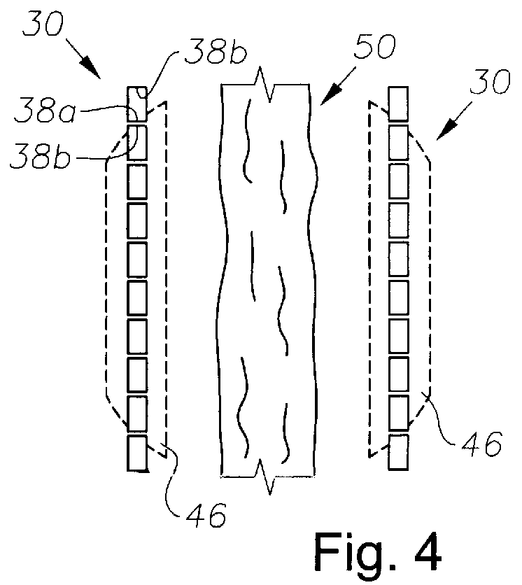
As mentioned above, the invention is preferably directed to flood control systems. Both methods and apparatus for flood control are within the scope of the invention. We will now describe specific embodiments, examples and versions of the invention, for the purpose of enabling others skilled in the art to make and use our invention. It is understood, however, that the invention is not limited to these specific embodiments, examples and versions. Nor is the invention restricted to flood control as such, but may be used in other applications involving the forming of a barrier to prevent or restrict the flow of any liquid. A person skilled in the art who has read this patent or seen the invention being used, described, or implemented will recognize many variations of the invention that might not be expressed here. Thus, it is the claims below that should be referred to for purposes of determining the scope of the invention, not only the literal elements therein, but also their substant...


PUM


Abstract

A flood control system, in one aspect involving providing a plurality of substantially rigid containers, at least some of the containers having a top portion, a bottom portion and substantially rigid sidewalls operably connecting the top and bottom portions, the sidewalls being configured to withstand compressive forces between the top portion and the bottom portion; and positioning the plurality of substantially rigid containers at a selected location proximate a body of water, at least some of the substantially rigid containers being positioned at the selected location in a substantially abutting relationship to form a barrier.

Description

1. Field of the InventionThis invention relates broadly to methods for preventing or inhibiting the flow of water and other fluids, including oily water or toxic chemicals. In a preferred aspect, the invention relates to flood control systems, and more preferably to portable flood control systems.2. Description of the Related ArtIn a broad sense, flood control systems may be classified as either stationary or portable. One common type of stationary flood control system is a fixed, concrete dam. An early effort at improving stationary dams is disclosed in U.S. Pat. No. 1,077,791, disclosing a concrete dam structure having a "honeycomb" construction, with individual cells that may be either empty or filled with water.For portable flood control, the most well-known and widely used technique is still conventional sandbags. During flooding, sandbags are typically placed by human hands at locations that are still above the rising water level, to collectively create a wall, dam, or barrier...

Claims


Application Information

Patent Timeline
IPC IPC(8): E02B3/10
CPCE02B3/108
Inventor PERRY, JAMES D.BENET, STEPHEN E.
Owner TOBOR & GOLDSTEIN
Why Eureka
Try Eureka